Ads 230 x 230

Saturday, May 7, 2011

Fth generation fighters RADAR systems

Posted by: , 0 comments

1.0 Introduction
2.0 Capabilities
3.0 Technology
4.0 Radar software
5.0 Testing
:: One of the very rare available pictures of the AN/APG-77 radar antenna modules.


1
1.0 Introduction
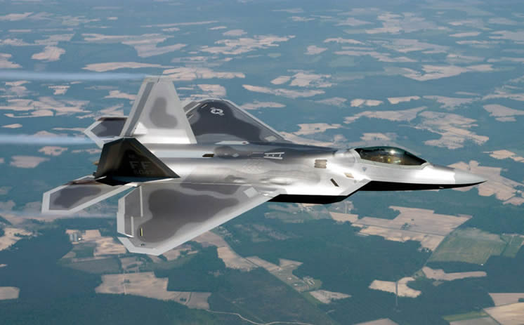
The F/A-22's avionics and software system is the most advanced ever integrated into an aircraft. It is the first aircraft to use integrated avionics, where the weapons management system, electronic warfare system and the AN/APG-77 radar work as one, giving the pilot unprecedented situation awareness.

A joint venture of Northrop Grumman's Electronic Sensors and Systems Division (ESSD) and Raytheon is developing the advanced AN/APG-77 active-element electronically scanned array radar for the F/A-22.


2.0 Capabilities
The AN/APG-77 radar is designed for air-superiority and strike operations and features a low observable, active aperture, electronically-scanned array with multi-target, all-weather capability.
The radar is key to the F/A-22's integrated avionics and sensor capabilities. It will provide pilots with detailed information about multiple threats before the adversary's radar ever detects the F/A-22. This is also called BVR, or Beyond Visual Range capability.


:: Beyond Visual Range attack, executed by 2 F/A-22's

It will give an F/A-22 pilot the possibility in air-to-air combat, to track, target and shoot at multiple threat aircraft before the adversary's radar ever detects the F/A-22.

It will give an F/A-22 pilot the possibility in air-to-air combat, to track, target and shoot at multiple threat aircraft before the adversary's radar ever detects the F/A-22.


3.0 Technology
The F/A-22's AN/APG-77 radar is an active-element, electronically scanned (that is, it does not move) array of around 2000 finger-sized transmitter / receiver modules. Each module weights ca 15g and has a poweroutput of over 4W. The APG-77 is capable of changing the direction, power and shape of the radar beam very rapidly, so it can acquire target data, and in the meantime minimizing the chance that the radar signal is detected or tracked.
.

:: Multiple function performance of the AN/APG-77 radar system, varying from simple area sweeps to tracking and missile fire control, all at the same time.
Most of the mechanical parts common to other radars have been eliminated, thus making the radar more reliable.This type of antenna, which is integrated both physically and electromagnetically with the airframe, provides the frequency agility, low radar cross-section, and wide bandwidth necessary to support the F/A-22's air dominance mission.

One requirement that drove all of the ATF designs was a wide field of regard for sensors, enabling the Raptor to acquire and track multiple targets beyond visual range. The requirement called for a 120-degree radar field of regard on each side of the nose.

A forward-looking infrared search and track capability was also desired. Lockheed approached the field-of-regard requirement for the radar with three radar arrays placed in the nose of the aircraft (one facing forward and two facing sideways). Each wing root carried an infrared search and track system that operated through faceted windows.


4.0 Radar Software
The avionics software is to be integrated in three blocks, each building on the capability of the previous block. Block 1 is primarily radar capability, but Block 1 does contain more than 50 percent of the avionics suite's full functionality source lines of code (SLOC) and provides end-to-end capability for the sensor-to-pilot data flow

This Block 1 software enables the basic operation of the radar and its initial mode complement, including the simultaneous operation of search and track modes and systems health and maintenance or built-in-test modes.
At the Boeing Avionics Integration Laboratory the F/A-22 radar was integrated with the avionics mission software and other aircraft avionics sensors such as the electronic warfare system, and the communications, navigation and information systems.


5.0 Testing
By the first quarter of 1998, the radar was delivered to The Boeing Company's F/A-22 Avionics Integration Laboratory in Seattle, Wash., where engineers integrated the radar with other F/A-22 avionics.

Meanwhile, flight testing of a second F/A-22 radar continued aboard a modified Boeing 757 testbed aircraft at ESSD. The test bed consistsed of an F/A-22 forward fuselage installed on the 757's forward pressure bulkhead. Electronic warfare (EW) and communication, navigation and identification (CNI) sensors were mounted directly on the sensor wing, which was designed to simulate the sensor positioning found on the F/A-22's wings.
.

:: Clearly visible on the testbed are the F/A-22 nose-cone (radome), the wing on top and various sensors on the bottom of the plane.

The cabin had space for 30 software engineers and technicians who could evaluate avionics and identify anomalies, in real time. A simulated F/A-22 cockpit was installed in the cabin of the Flying Test Bed. It had all primary and secondary F/A-22 displays, as well as the throttle and stick.

The conducted flight tests successfully demonstrated the expected levels of performance of the F/A-22 radar, including basic search and track functions.


OK right i will illustrating the capabilities using this video animated

===========+++++============


All about Stealt Technology in Air combat

Posted by: , 0 comments

Introduction
Introduction
Continuous developments in military aircraft technology have produced a new sort of defensive weapon: Stealth.

Planes can now fly invisibly into enemy airspace, drop a payload, and fly back out without being detected, identified or attacked.


:: An F/A-22 in stealth mode or....?!


To meet this goal, an aircraft must be "stealthy" in many areas.

1. It must be very hard to detect on radar.
2. The hot emissions from the engines must be minimal.
3. It must be quiet
4. Its engines should not produce contrails or exhaust smoke in cold atmosphere
5. It should be hard to see with the human eye

Click on the buttons to the left to learn more about the different aspects of Stealth. Find out yourself how planes and especially the F/A-22 can become almost invisible for enemy radar, what does a stealthy airframe look like and what may the future have in store?

Have a good time discovering the secrets of technology!

Detection

1.0 Radar technology
2.0 Detection techniques
2.1 Direct echo's
2.2 Jet wake detection
2.3 Heat detection
2.4 Turbulence detection
2.5 Visual detection
2.6 Acoustic detection

1.0 Radar technology
Currently the way to detect and even identify aircraft, is the use of radar. This system, invented during world war II, simply works by constantly sending bursts of radio waves of certain frequencies and measure the echo's of each burst.

Parts of the energy of radio waves are being reflected by objects. This can be a plane, but also a cloud or a bird. Depending on the material the object is made of, this echo is stronger or weaker, but there is an echo. By measuring the reflected energy as a function of position and time, computers can calculate what it is that reflects the energy, where it is in 3D space and also in what direction it moves.

To get a proper overview of an area with radar, the transmitting and receiving antenna should rotate in angles of 360 degrees. This is why you always see these rotating antenna's at for instance airports and ships. To protect the antenna's from damage, they are often mounted in a radio wave transparent dome, which you will probably already have seen somewhere.


2.0 Detection techniques
There are a number of causes for planes or other flying objects like missiles, giving away the fact that they are there. Radar or in other cases laser technology enables the searching party to detect the flying object and act upon detection.


2.1 Direct echo's
Once radar waves hit a plane, a part of the radar energy is bounced back to the sending source. The amount of bounced back energy highly depends on the shape of the object and the material it is made of.

The returned echo can be deteced, giving away the position and speed of the object.


2.2 Jet wake
The parameter determining radar return from a jet wake is the ionization present. Return from resistive particles, such as carbon, is seldom a significant factor. The very strong ion-density dependency on maximum gas temperature quickly leads to the conclusion that the radar return from the jet wake of an engine running in dry power is insignificant, while that from an after burning wake could be dominant.
2.3 Heat detection
Another way of detecting if an aircraft is flying somewhere is by measuring the heat it radiates. Normally this heat is produced by the planes engines. There are two significant sources of infrared radiation from air-breathing propulsion systems: hot parts and jet wakes.

By using modern heat image sensors (read InfraRed sensors) the difference can be seen between a flying object itself and the surrounding cold air.

This is the same for the jet engine exhaust gases


:: InfraRed image of a MIG fighter.

The ideal case would be that the plane body and exhaust fumes have the same temperature as the surrounding air, making it blend with its background (seen from the detectors point of view.

Heat detection is often used in missiles which can lock themselves on the hot jet-engine exhaust and thus flying themselves directly into the planes most vital part. The Sidewinder is a good example of such a missile.


2.4 Turbulence detection
Shape also has a lot to do with the `invisibility' of stealth planes. Extreme aerodynamics keep air turbulence to a minimum. Rumors are heard about sophisticated laser controlled turbulence sensors, which can measure paths of disturbed air, generated by an aircraft which just passed.


2.5 Visual detection
Reducing smoke in the exhaust is accomplished by improving the efficiency of the combustion chambers. Getting rid of contrails - the white line in the sky caused by high flying planes - is a harder task however. More about that later.


2.6 Acoustic detection
A very obvious source of detection is the noise, generated by jet engines. Several systems have been designed in the meantime to reduce the sound of jet engine exhausts to a minimum, making them harder to detect by just measuring sound waves. But often it is already too late if you can hear the plane...

Get Stealthy

1.0 How to get Stealthy
1.1 Ingredients of Stealth
1.2 Radar Cross section RCS
2.0 Getting invisible
2.1 Echo scattering
2.2 Radar absorbtion
2.3 Echo cancellation
3.0 Heat radiation reduction
4.0 Turbulence reduction
5.0 Visual detection reduction
5.1 Hiding smoke contrails
5.2 Low visibility
5.3 Low level flight


1.0 How to get Stealthy

1.1 Ingredients of Stealth technology
To make a stealthy aircraft, designers had to consider five key ingredients:

- reducing the imprint on radar screens / stifling radio transmissions
- turning down the heat of its infrared picture
- Improve aerodynamics
- making the plane less visible.
- muffling noise

To understand more about each ingredient, here is some theory first.


1.2 Radar Cross section (RCS)
The first goal is to cut down the size of the aircraft's radar image, called its "radar cross section," or RCS. This normally involves using radical design features and some nonmetallic materials.

A conventional fighter aircraft has an Radar Cross Section (RCS) in the region of 6 square metres. The much larger B-2B bomber, using the latest stealth technology, displays an RCS of only 0.75 square metres. By comparison, a bird in flight displays an RCS of 0.01 square metres.

Stealth plane designers have to take in account that the used materials (for instance composites) may not be transparant to radar, but they are also not completely reflective. In other words, the parts behind the skin of the plane may be invisible for the eye, but they are not for radar waves, thus causing echos.


2.0 Getting invisible
This section explains more about what radar echos look like and how they can be prevented to reach the radar receiver again after hitting the plane.


2.1 Echo scattering
Curving surfaces on conventional aerodynamic bodies act as scatterers, reflecting radar waves from any angle and giving the radar operator a clear signal. The right-angled surfaces at the wing and tail roots also reflect radar signals straight back to their source.

Scintillation is a measure of how rapidly the size of the return varies with the angle. The greater this variation, the more difficult a target is to track. The lower the number of lobes and the narrower the lobes, the lower the probability of detecting any return.
Panels on planes are angled so that radar is scattered and no signal goes back to base.

The F-117 airframe for instance has a large number of faceted surfaces, not unlike a crystal.
The facets are presumed to reflect radar energy away from the aircraft in any other direction than that of the radar emitter.


A flat plate at right angles to an impinging radar wave has a very large radar signal, and a cavity, similarly located, also has a large return. Thus the inlet and exhaust systems of a jet aircraft would be expected to be dominant contributors to radar cross section in the nose-on and tall-on viewing directions, and the vertical tail dominates the side-on signature.

2.2 Radar absorbtion
A second way of stopping radar reflections is by coating the plane with material that soaks up radar energy.
These typically consist of carbon, carbon fibre componsites, or magnetic ferrite-based substance.

The result is that for instance the B-2 is reported to have the same RCS as a child's tricycle!
Flight-control surface can be made from honeycombed materials which reflect incoming radar waves internally rather than back to the radar. Radar-absorbing coatings can be applied to the surface of the body which effectively drain the energy of the radar signal.


Flight-control surface can be made from honeycombed materials which reflect incoming radar waves internally rather than back to the radar. Radar-absorbing coatings can be applied to the surface of the body which effectively drain the energy of the radar signal.


2.3 Echo cancellation
The key dimension of a quarter wavelength can vary in practice from millimeter to one meter. Although the coating designer will frequently try to use materials whose dielectric constant varies in a way that maintains a constant wavelength independent of frequency, the reality is that a number of different coatings and absorbers are needed to cover the required bandwidth.

Imagine a low frequency absorber that might be made of glass fiber hex-cell material. Its resistance is graded from front to back so that the edge is initially electro-magnetically soft and gradually becomes more attenuating as the wave passes through. This approach is particularly taken when, for practical reasons, the layer cannot be as deep as a quarter wavelength. The inner absorber is covered by a high-frequency ferromagnetic coating, which completes the frequency coverage.

Metal components such as the engine, which produce significant radar reflections, can be shielded using a metal and plastic sandwich whose layers are spaced in such a way as to create a standing wave, cancelling out any radar reflections.


3.0 Heat radiation reduction
Infrared radiation (heat) should be minimized by a combination of temperature reduction and masking, although there is no point in doing these past the point where the hot parts are no longer the dominant terms in the radiation equation. The main body of the airplane has its own radiation, heavily dependent on speed and altitude, and the jet plume can be a most significant factor, particularly in afterburning operation.


The jet-wake radiation follows the same laws as the engine hot parts. Various ways have been developed and tested to cool down the engine exhaust gasses. The ilustration above shows how the hot exhaust gasses can be surrounded by cooler air, significantly reducing the IR signature of the plane.

Air has a very low emissivity, carbon particles have a high broadband emissivity, and water vapor emits in very specific bands. Infrared seekers have mixed feelings about water-vapor wavelengths, because, while they help in locating jet plumes, they hinder in terms of the general attenuation due to moisture content in the atmosphere. There is no reason, however, why smart seekers shouldn't be able to make an instant decision about whether conditions were favorable for using water-vapor bands for detection.


4.0 Turbulence reduction
By optimizing the aerodynamics of the stealth plane, the for the eye invisible turbulence trail in the air, can be kept to a minimum. This way it becomes harder for the very special laser equipment to detect the trail and trace it back all the way to the plane which created it.


5.0 Visual detection reduction

5.1 Hiding smoke contrails (jet wake)
Reducing smoke in the exhaust is accomplished by improving the efficiency of the combustion chambers. Getting rid of contrails - that distinct white line in the sky caused by high flying jets - is a harder task.

Tests have been done using exotic chemicals to be inserted into the engine outlet gases to modify infrared signature as well as to force water molecules in the exhaust plume to break up into much finer particles, thus reduce or even eliminate contrails. One of the chemical used for this was chloro-fluoro-sulphonic acid. Several other acids were tested too, but the result was that the chemicals were too corrosive and the system was waved.


5.2 Low visibility
An aircraft at low to medium altitudes tends to be a black dot against the background of the sky. To avoid this, the plane a given a special medium gray color.

The gray, when combined with light scattering at low to medium altitudes ensures about as low observability as can be possible, or a reduction to 30% in visibility.


5.3 Low level flight
Another technique used by aircraft to avoid radar is to fly at very low levels where there is a great deal of 'ground clutter' ... radar reflections given off by buildings and other objects. Low-level aircraft can go undetected by most radar systems.

The latest ground-defence systems however are designed to discriminate between ground-clutter and hostile planes. In addition, ground-clutter is partly avoided by using 'look down' radar systems, which track aircraft from other aircraft flying above.


1.0 F/A-22 Stealth features
2.0 Continuous curves
3.0 Planform alignment
4.0 Sawtoothed edges
5.0 Engine nozzles
6.0 Cockpit
7.0 Antennas
8.0 Paint scheme
9.0 Conclusion

1.0 Stealth features of the F/A-22
Taking a look at the F/A-22, quickly reveals the fundamental principles of a stealthy design as discussed earlier.


2.0 Continuous curves

The F/A-22 uses a combination of different ways to keep radar waves from bouncing back to their origin. The most sophisticated system is the use of so-called continuous curvature.

Many of of the surface shapes of the F/A-22 are curves with constantly changing radii. These scatter radar beams in all directions instead of back to the radar source. There are no right angles on the exterior of the design.

In order to calculate the curves and the effect they have on radar reflections form any point in 3D space, requires a tremendous computing power.
The first plane using this technology extensively is the B-2 stealth bomber, also known as the flying wing.


:: Equally sloped edges and continuous curvature to reduce radar echos to a minimum

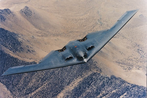
Since computer- and software development has sky-rocketed over the past 20 years, prediction models can now be calculated quite precisely ,taking in account radar reflection versus the shape of the plane, while supporting more naturally aerodynamic shapes.


3.0 Planform alignment
The second way to keep radar waves from returning to the sending antenna, the leading and trailing edges of the wing and tail have identical sweep angles (a design technique called planform alignment).

The fuselage and canopy have sloping sides. The vertical tails are canted. The engine face is deeply hidden by a serpentine inlet duct and weapons are carried internally.


4.0 Saw-toothed edges
The F/A-22 has a low height triangle appearance from the front. This physical cross sectional view ensures a small signature from the front and low observability touches such as paint and materials, as well as little "W" shapes where straight lines might have appeared, all tend to break up the signature by absorption or redirection.

:: Detail of the F/A-22's top, showing a number of places where the w shaped edges are clearly visible

The "W" shapes are found at numerous places on the stealth aircraft. For instance, in the forefront of the cockpit glass, there is a very apparent "W" shape. This reduces the radar energy reflected during a head-on pass to the radar emitter. The "W" shape is also found on landing gear doors, engine inlets and outlets, as well as other openings.


5.0 Engine nozzles
Reduction of radar cross section of nozzles is also very important, and is complicated by high material temperatures.
The approach taken at Lockheed is to use ceramic materials.

The ceramics may be either lightweight, parasitic sheets mounted on conventional nozzle structures or heavier structural materials forming saw-toothed edges.


:: Specially shaped ceramic coated thrustvectoring nozzles of the F/A-22
6.0 Cockpit
The pilot's head, complete with helmet, is a major source of radar return. This effect is amplified by the returns of internal bulkheads and frame members. The solution is to design the cockpit so that its external shape conforms to good low radar cross section design rules, and then plate the glass with a film similar to that used for temperature control in commercial buildings. Here, the requirements are more stringent: it should pass at least 85% of the visible energy and reflect essentially all of the radar energy. At the same time, one would prefer not to have noticeable instrument-panel reflection during night flying.


7.0 Antennas
On-board antennas and radar systems are a major potential source of high radar visibility for two reasons. One is that it is obviously difficult to hide something that is designed to transmit with very high efficiency, so the so-called in-band radar cross section is liable to be significant. The other is that even if this problem is solved satisfactorily, the energy emitted by these systems can normally be readily detected. The work being done to reduce these signatures is classified.


8.0 Paint scheme
In order to make the F/A-22 disappear for the human eye on the ground, when in flight, special camouflage schemes have been developed. This way the plane will blend with the background sky as much as possible viewed from the bottom and disappear in the ground texture when seen from above.
.

:: The F/A-22's paint scheme, derived from the F-15's "Mod-Eagle" paint scheme

9.0 Conclusion
The result of all these as well as a number of un-disclosed or non mentioned measures is the F/A-22's
BVR capability, meaning that it can detect, engage and kill an opponent fighter, while staying invisible itself.

The future of Stealth
Imagine you can electronically change the color of a given surface in such a way it can match the terrain below it. Looking from above, the surface appears to match the terrain. Fly over forest, and the surface takes on a green like hue. A cloudy day, add clouds to match what sensors see underneath and the aircraft becomes a chameleon and disappears.
.

:: The shape of stealth to be???

This may sound like Science Fiction, but then think of the LCD display of notebooks and it may not seem so far fetched all of a sudden. Recent breakthroughs in chemical polymer technology have made it possible to create polymer (plastic) color displays. In other words, mold the polymer in any shape you like and with the additional control electronics you can make it virtually invisible from any point of view.

You can try it yourself with your own computer. Take a look at this website, containing a tutorial on how to make your computer screen transparent, which of course is just an illusion...

This is not a new idea, in fact several military fiction writers have already come up with the idea, in one particular instance having the aircraft continually modifying top and bottom like a magician's mirror box making the aircraft totally invisible.

More technologies are currently under development and will be closely monitored to be found here. But likewise the F-117, we may not hear about that until the first smart-bomb coming out of nowhere has made a successful hit!

=================++++=============

----------------------------------------------


Friday, May 6, 2011

STEALTH AIRCRAFT PRINCIPLES WHAT MAKES STEALTH TECHNOLOGY WORK| | تــكنولوجيا التسلل الراداري

Posted by: , 0 comments

B-2 Stealth Bomber


Stealth technology also known as LOT (Low Observability Technology) is a sub-discipline of military electronic countermeasures which covers a range of techniques used with aircraft, ships and missiles, in order to make them less visible (ideally invisible) to radar, infrared and other detection methods.

The concept of stealth is not new: being able to operate without the knowledge of the enemy has always been a goal of military technology and techniques. However, as the potency of detection and interception technologies (radar, IRST, surface-to-air missiles etc.) has increased, so too has the extent to which the design and operation of military vehicles have been affected in response. A 'stealth' vehicle will generally have been designed from the outset to have reduced or controlled signature. It is possible to have varying degrees of stealth. The exact level and nature of stealth embodied in a particular design is determined by the prediction of likely threat capabilities and the balance of other considerations, including the raw unit cost of the system.
F-22 Raptor Stealth Fighter
A mission system employing stealth may well become detected at some point within a given mission, such as when the target is destroyed, but correct use of stealth systems should seek to minimize the possibility of detection. Attacking with surprise gives the attacker more time to perform its mission and exit before the defending force can counter-attack. If a surface-to-air missile battery defending a target observes a bomb falling and surmises that there must be a stealth aircraft in the vicinity, for example, it is still unable to respond if it cannot get a lock on the aircraft in order to feed guidance information to its missiles.
Stealth principles
Stealth technology (often referred to as "LO", for "low observability") is not a single technology but is a combination of technologies that attempt to greatly reduce the distances at which a vehicle can be detected; in particular radar cross section reductions, but also acoustic, thermal and other aspects specifically:
Radar cross-section (RCS) reductions
Main article: Radar cross section
Almost since the invention of radar, various techniques have been tried to minimize detection. Rapid development of radar during WWII led to equally rapid development of numerous counter radar measures during the period; a notable example of this was the use of chaff.
The term 'Stealth' in reference to reduced radar signature aircraft became popular during the late eighties when the F-117 stealth fighter became widely known. The first large scale (and public) use of the F-117 was during the Gulf War in 1991. However, F-117A stealth fighters were used for the first time in combat during Operation Just Cause, the United States invasion of Panama in 1989. Since then it has become less effective due to developments in the algorithms used to process the data received by radars, such as Bayesian particle filter methods. Increased awareness of stealth vehicles and the technologies behind them is prompting the development of techniques for detecting stealth vehicles, such as passive radar arrays and low-frequency radars. Many countries nevertheless continue to develop low-RCS vehicles because low RCS still offers advantages in detection range reduction as well as increasing the effectiveness of decoys against radar-seeking threats.
F-117 Stealth Aircraft
Vehicle shape
The possibility of designing aircraft in such a manner as to reduce their radar cross-section was recognized in the late 1930s, when the first radar tracking systems were employed, and it has been known since at least the 1960s that aircraft shape makes a very significant difference in how well an aircraft can be detected by a radar. The Avro Vulcan, a British bomber of the 1960s, had a remarkably small appearance on radar despite its large size, and occasionally disappeared from radar screens entirely. It is now known that it had a fortuitously stealthy shape apart from the vertical element of the tail. On the other hand, the Tupolev 95 Russian long range bomber (NATO reporting name 'Bear') appeared especially well on radar. It is now known that propellers and jet turbine blades produce a bright radar image; the Bear had four pairs of large (5.6 meter diameter) contra-rotating propellers.
Another important factor is the internal construction. Behind the skin of some aircraft are structures known as re-entrant triangles. Radar waves penetrating the skin of the aircraft get trapped in these structures, bouncing off the internal faces and losing energy. This approach was first used on SR-71.
The most efficient way to reflect radar waves back to the transmitting radar is with orthogonal metal plates, forming a corner reflector consisting of either a dihedral (two plates) or a trihedral (three orthogonal plates). This configuration occurs in the tail of a conventional aircraft, where the vertical and horizontal components of the tail are set at right angles. Stealth aircraft such as the F-117 use a different arrangement, tilting the tail surfaces to reduce corner reflections formed between them. The most radical approach is to eliminate the tail completely, as in the B-2 Spirit.
SR-71 Blackbird Early Stealth Testing
In addition to altering the tail, stealth design must bury the engines within the wing or fuselage, or in some cases where stealth is applied to an existing aircraft, install baffles in the air intakes, so that the turbine blades are not visible to radar. A stealthy shape must be devoid of complex bumps or protrusions of any kind; meaning that weapons, fuel tanks, and other stores must not be carried externally. Any stealthy vehicle becomes un-stealthy when a door or hatch is opened.
Planform alignment is also often used in stealth designs. Planform alignment involves using a small number of surface orientations in the shape of the structure. For example, on the F-22A Raptor, the leading edges of the wing and the tail surfaces are set at the same angle. Careful inspection shows that many small structures, such as the air intake bypass doors and the air refueling aperture, also use the same angles. The effect of planform alignment is to return a radar signal in a very specific direction away from the radar emitter rather than returning a diffuse signal detectable at many angles.
Stealth airframes sometimes display distinctive serrations on some exposed edges, such as the engine ports. The YF-23 has such serrations on the exhaust ports. This is another example in the use of re-entrant triangles and planform alignment, this time on the external airframe.
Shaping requirements have strong negative influence on the aircraft's aerodynamic properties. The F-117 has poor aerodynamics, is inherently unstable, and cannot be flown without computer assistance. Some modern anti-stealth radars target the trail of turbulent air behind it instead, much like civilian wind shear detecting radars do.
Ships have also adopted similar techniques. The Visby corvette was the first stealth ship to enter service, though the earlier Arleigh Burke class destroyer incorporated some signature-reduction features [1]. Other examples are the French La Fayette class frigate, the USS San Antonio amphibious transport dock, and most modern warship designs.
Propulsion subsystem shaping
Now in research, fluidic nozzles for thrust vectoring with aircraft jet engines, and ships, will have lower RCS, due to being less complex, mechanically simpler, with no moving parts or surfaces, and less massive (up to 50% less). They will likely be used in many unmanned aircraft, and 6th generation fighter aircraft. Fluidic nozzles divert thrust via fluid effects. Tests show that air forced into a jet engine exhaust stream can deflect thrust up to 15 degrees.
Non-metallic airframe
Dielectric composites are relatively transparent to radar, whereas electrically conductive materials such as metals and carbon fibers reflect electromagnetic energy incident on the material's surface. Composites used may contain ferrites to optimize the dielectric and magnetic properties of the material for its application.
Radar absorbing material
Radar absorbent material (RAM), often as paints, are used especially on the edges of metal surfaces. One such coating, also called iron ball paint, contains tiny spheres coated with carbonyl iron ferrite. Radar waves induce alternating magnetic field in this material, which leads to conversion of their energy into heat. Early versions of F-117A planes were covered with neoprene-like tiles with ferrite grains embedded in the polymer matrix, current models have RAM paint applied directly. The paint must be applied by robots because of problems of solvent toxicity and tight tolerances on layer thickness.
Similarly, coating the cockpit canopy with a thin film transparent conductor (vapor-deposited gold or indium tin oxide) helps to reduce the aircraft's radar profile because radar waves would normally enter the cockpit, bounce off something random (the inside of the cockpit has a complex shape), and possibly return to the radar, but the conductive coating creates a controlled shape that deflects the incoming radar waves away from the radar. The coating is thin enough that it has no adverse effect on the pilot's vision.

Radar stealth countermeasures and limitations

Low frequency radar
Shaping does not offer stealth advantages against low-frequency radar. If the radar wavelength is roughly twice the size of the target, a half-wave resonance effect can still generate a significant return. However, low-frequency radar is limited by lack of available frequencies which are heavily used by other systems, lack of accuracy given the long wavelength, and by the radar's size, making it difficult to transport. A long-wave radar may detect a target and roughly locate it, but not identify it, and the location information lacks sufficient weapon targeting accuracy. Noise poses another problem, but that can be efficiently addressed using modern computer technology; Chinese "Nantsin" radar and many older Soviet-made long-range radars were modified this way. It has been said that "there's nothing invisible in the radar frequency range below 2 GHz".
Multiple transmitters
Much of the stealth comes from reflecting the transmissions in a different direction other than a direct return. Therefore detection can be better achieved if the sources are spaced from the receivers, known as bistatic radar , and proposals exist to use reflections from sources such as civilian radio transmitters, including cellular telephone radio towers.
Acoustics
Acoustic stealth plays a primary role in submarine stealth as well as for ground vehicles. Submarines have extensive usage of rubber mountings to isolate and avoid mechanical noises that could reveal locations to underwater passive sonar arrays.
Early stealth observation aircraft used slow-turning propellers to avoid being heard by enemy troops below. Stealth aircraft that stay subsonic can avoid being tracked by sonic boom. The presence of supersonic and jet-powered stealth aircraft such as the SR-71 Blackbird indicates that acoustic signature is not always a major driver in aircraft design, although the Blackbird relied more on its extremely high speed and altitude.
Visibility
Most stealth aircraft use matte paint and dark colors, and operate only at night. Lately, interest on daylight Stealth (especially by the USAF) has emphasized the use of gray paint in disruptive schemes, and it is assumed that Yehudi lights could be used in the future to mask shadows in the airframe (in daylight, against the clear background of the sky, dark tones are easier to detect than light ones) or as a sort of active camouflage. The B-2 has wing tanks for a contrail-inhibiting chemical, alleged by some to be chlorofluorosulphonic acid, and mission planning also considers altitudes where the probability of their formation is minimized.
Infrared
An exhaust plume contributes a significant infrared (IR) signature. One means of reducing the IR signature is to have a non-circular tail pipe (a slit shape) in order to minimize the exhaust cross-sectional volume and maximize the mixing of the hot exhaust with cool ambient air. Often, cool air is deliberately injected into the exhaust flow to boost this process. Sometimes, the jet exhaust is vented above the wing surface in order to shield it from observers below, as in the B-2 Spirit, and the unstealthy A-10 Thunderbolt II. To achieve infrared stealth, the exhaust gas is cooled to the temperatures where the brightest wavelengths it radiates on are absorbed by atmospheric carbon dioxide and water vapor, dramatically reducing the infrared visibility of the exhaust plume. Another way to reduce the exhaust temperature is to circulate coolant fluids such as fuel inside the exhaust pipe, where the fuel tanks serve as heat sinks cooled by the flow of air along the wings.
Reducing radio frequency (RF) emissions
In addition to reducing infrared and acoustic emissions, a stealth vehicle must avoid radiating any other detectable energy, such as from onboard radars, communications systems, or RF leakage from electronics enclosures. The F-117 uses passive infra-red and "low light level TV" sensor systems to aim its weapons and the F-22 Raptor has an advanced LPI radar which can illuminate enemy aircraft without triggering a radar warning receiver response.
Measuring stealth
The size of a target's image on radar is measured by the radar cross section or RCS, often represented by the symbol σ and expressed in square meters. This does not equal geometric area. A perfectly conducting sphere of projected cross sectional area 1 m2 (ie a diameter of 1.13 m) will have an RCS of 1 m2. Note that for radar wavelengths much less than the diameter of the sphere, RCS is independent of frequency. Conversely, a square flat plate of area 1 m2 will have an RCS of σ = 4π A2 / λ2 (where A=area, λ=wavelength), or 13,982 m2 at 10 GHz if the radar is perpendicular to the flat surface. At off-normal incident angles, energy is reflected away from the receiver, reducing the RCS. Modern stealth aircraft are said to have an RCS comparable with small birds or large insects, though this varies widely depending on aircraft and radar.
If the RCS was directly related to the target's cross-sectional area, the only way to reduce it would be to make the physical profile smaller. Rather, by reflecting much of the radiation away or absorbing it altogether, the target achieves a smaller radar cross section.
Stealth tactics
Stealthy strike aircraft such as the F-117, designed by Lockheed Martin's famous Skunk Works, are usually used against heavily defended enemy sites such as Command and Control centers or surface-to-air missile (SAM) batteries. Enemy radar will cover the airspace around these sites with overlapping coverage, making undetected entry by conventional aircraft nearly impossible. Stealthy aircraft can also be detected, but only at short ranges around the radars, so that for a stealthy aircraft there are substantial gaps in the radar coverage. Thus a stealthy aircraft flying an appropriate route can remain undetected by radar. Many ground-based radars exploit Doppler filter to improve sensitivity to objects having a radial velocity component with respect to the radar. Mission planners use their knowledge of the enemy radar locations and the RCS pattern of the aircraft to design a flight path that minimizes radial speed while presenting the lowest-RCS aspects of the aircraft to the threat radar. In order to be able to fly these "safe" routes, it is necessary to understand the enemy's radar coverage (see Electronic Intelligence). Mobile radars such as AWACS can complicate matters.
For Example :

B-2 Stealth Bomber


B-2 Stealth Bomber
The ‘flying wing’ shaped Stealth Bomber (nicknamed ‘Spirit’) is a unique aircraft that’s designed to make it as invisible as possible. Its shape means there are very few leading edges for radar to reflect from, reducing its signature dramatically. This is further enhanced by the composite materials from which the aircraft is constructed and the coatings on its surface. These are so successful that despite having a 172-foot wingspan, the B-2’s radar signature is an astounding 0.1 square metres.
The B-2’s stealth capabilities, and aerodynamic shape, are further enhanced by the fact its engines are buried inside the wing. This means the induction fans at the front of the engines are concealed while the engine exhaust is minimised. As a result, the B-2’s thermal signature is kept to the bare minimum, making it harder for thermal sensors to detect the bomber as well as lowering the aircraft’s acoustic footprint.
The design also means the B-2 is both highly aerodynamic and fuel efficient. The B-2’s maximum range is 6,000 nautical miles and as a result the aircraft has often been used for long-range missions, some lasting 30 hours and in one case, 50. The B-2 is so highly automated that it’s possible for a single crew member to fl y while the other sleeps, uses the lavatory or prepares a hot meal and this combination of range and versatility has meant the aircraft has been used to research sleep cycles to improve crew performance on long-range missions. Despite this, the aircraft’s success comes with a hefty price tag. Each B-2 costs $737 million and must be kept in a climate-controlled hangar to make sure the stealth materials remain intact. These problems aside though, the Spirit is an astonishing aircraft, even if, chances are, you won’t see one unless the pilots want you to…
Inside the Spirit
The B-2 is an unusual combination of complexity and elegance, the entire airframe built around the concept of stealth and focused on making the aircraft as hard to detect as possible.
B-2 Stealth Bomber
Windows
The B-2′s windows have a fine wire mesh built into them, designed to scatter radar.
Composite materials
Any radar returns are reduced by the composite materials used, which further deflect any signals.
Carbon-reinforced plastic
Special heat-resistant material near the exhausts mean the airframe absorbs very little heat.
Rotary launch assembly (RLA)
The RLA allows the B-2 to deploy different weapons in quick succession.
Bomb rack assembly (BRA)
The bomb rack assembly can hold up to eighty 500lb bombs.
Air Intakes
To further reduce the B-2′s signature, the engine intakes are sunk into the main body.
B-2 Stealth Bomber
Landing gear doors
The landing gear doors are hexagonal to further break up the B-2′s radar profile.
Crew compartment
The B-2 carries two crew, a pilot and a mission commander with room for a third if needed.
Flying wing
The B-2′s shape means it has very few leading edges, making it harder to detect on radar.
Fly-by-wire
The B-2′s unique shape makes it unstable, and it relies on a computer to stabilise it and keep it flying.
Engines
The B-2′s four General Electric F118s don’t have afterburners as the heat these generate would make the aircraft easier to detect.
The Statistics
B-2 Stealth Bomber
Manufacturer
Northrop Grumman
Year first deployed
1993
Dimensions
Length: 69ft
Wingspan: 172ft
Height: 17ft
Weight empty / max
158,000lb / 336,500lb
Unit cost
$737,000,000
Max speed
Mach 0.95 (604mph)
Propulsion
General Electric F118-GE-100 non-afterburning turbofans
Max altitude
50,000ft

============+++=============
----------------------------------------------

Sunday, May 1, 2011

All about optical industry and Communication

Posted by: , 0 comments

An introduction to fiber optic system
http://www.fileserve.com/file/m4KvH48
Controlled fiber optic sensor

http://www.fileserve.com/file/ewREccE

Essentials of Modern Optical Fiber Communication_Reinhold Noe

http://www.fileserve.com/file/B6F8Z8f

Fiber Optic Cabling_2nd_Barry Elliot_Gilmore
http://www.fileserve.com/file/anDuZWp
Fiber Optic engineering_Mohammad Azadeh

http://www.fileserve.com/file/PfnrQGV

http://www.fileserve.com/file/hnVD2Uj
Fiber Optic Technical manual

http://www.fileserve.com/file/MauwsSv
Fiber Optics Handbook

http://www.fileserve.com/file/vWN8a8X
Fiber Optics Installer and Technician Guide

http://www.fileserve.com/file/24QKs8D
Fiber Optics Physics

http://www.fileserve.com/file/MqEbuMA
Fiber_Optic_Communications_PALAIS

http://www.fileserve.com/file/UBPhtAR
FIBER_OPTIC_COMMUNICATION_SYSTEMS-3RD

http://www.fileserve.com/file/HnUyTzJ
Optic Fiber communication IIIA

http://www.fileserve.com/file/ZFWaYU9
Optical Communication Theory_Enrico Foeriesti

http://www.fileserve.com/file/Cqp4PpB
Optical switching

http://www.fileserve.com/file/7M3W46f
Toward Optical Network


Slideshow

 
صفحات مبعــثرة كسرت حاجز الصمـت لتحكي
متعة الحياة أن تعمل عملا لم يسبقك إليه أحد ولم يتوقعه الآخرون.................. Its just another way to unlock ur potential representing my internists with other. By sniffing the web u might see several info.,instructions and details. here i collect similar and simplify them to u, cutting out from my time, efforts even i create my unique posts