What is "Fiber Optics"?
Fiber
optics refers to the technology of transmitting light down thin strands
of highly transparent material, usually glass but sometimes plastic.
Fiber optics is used in communications, lighting, medicing, optical
inspections and to make sensors. The FOA is primarily interested in
communications fiber optics, so this book will focus on that
application.
Fiber optic communications began during the 1970s in R&D labs around the world (Corning, Bell Labs, ITT UK, etc.) and was first installed commercially in Dorset, England by STC and Chicago, IL, USA in 1976 by AT&T. By the early 1980s, the first fiber optic telecommunications networks connected the major cities on each coast of the USA and began being installed throughout the world.
By the mid-80s, with the introduction of the first singlemode fibers, fiber’s bandwidth and distance capabilities made it significantly less expensive than other communications media and it began replacing all the telco copper, microwave and satellite long distance links. In the 90s, transoceanic fiber optic cables had replaced satellites between most continents. Now fiber has become cost effective for direct connection to the home.
CATV discovered fiber in the mid-1990s and used it first to enhance the reliability of their networks, a big problem. Not long afterwards, CATV system operators discovered they could offer phone and Internet service on that same fiber and greatly enlarged their markets.
The Internet was first transmitted over phone lines which by the late 1980s were mostly fiber. But as Internet traffic grew with the advent of the web and everyone using email, it soon surpassed voice in traffic volume and found the phone system, optimized for voice transmission, highly inefficient for large amounts of digital data. The Internet with its unique transmission protocols became independent from the phone network, although it often used fibers in the same cables.
As cell phones became better and less expensive, creating a gigantic market for personal communications and portable data access, their backbones were built on fiber optics. Frequency allocations for wireless systems were limited so cellular backhaul used fiber to connect to worldwide phone networks.
Cities started using fiber optics early in the game, connecting schools, data networks from city agencies and public safety organizations first. Intelligent highway systems led to connecting “smart” traffic light into networks that could optimize traffic flow. When worries about terrorism led to the installation of many surveillance cameras around cities, the distance from cameras to monitoring stations was long enough that connecting them on fiber was much less expensive. Today some even offer direct fiber connections to their residents or businesses.
Computer networks (LANs) started using fiber about the same time as the telcos, in the late 1970s. Industrial links were among the first applications as the noise immunity of fiber and its distance capability make it ideal for the factory floor. Connecting graphics displays and mainframe storage links, the predecessors of today's fiber SANs (storage area networks) in data centers, came next. Today fiber is used in most corporate LANs as backbones, connections to desktops for engineering and graphics workstations and many wireless access points.
Utilities also have become big users of fiber. Practically every pipeline or electrical line has fiber running parallel to it or even inside the wires in the case of high voltage electrical distribution lines. Fiber provides communications over the routes and sometimes even includes sensors that keep track of the performance and problems. The electrical utilities are developing “smart grids” to make their power distribution more efficient and these networks depend on fiber for connections.
Other applications developed too: aircraft, ship and automobile data busses, CCTV for security, building automation systems, industrial networks and machinery, even links for consumer digital stereo!
Today fiber optics is either the dominant medium or a logical choice for every communication system. Costs have been reduced so much that fiber to the home is now cost effective, especially since it can offer services (entertainment as well as communications) that no other medium offers.
Whenever
you read an article or talk to someone about fiber optics, you need to
know the point of view. We're mainly concerned with communications
fiber optics, but it's also used in medical or nondestructive testing
inspection and lighting. Fiber optics, you see, is not all the
same.
Even
in communications, we have "outside plant" fiber optics as used in
telephone networks, CATV, metropolitan networks, utilities, etc. or
"premises" fiber optics as found in buildings and campuses.Just like "wire" which can mean lots of different things
- power, security, HVAC, CCTV, LAN or telephone - fiber optics
is not all the same. And this can be a big source of confusion
to the novice. Lets define our terms.
Outside Plant (OSP)
Telephone companies, CATV and the Internet all use lots of fiber optics, virtually all of which is singlemode fiber and most of which is outside buildings. It hangs from poles, is buried underground, pulled through conduit or is even submerged underwater. Most of it goes relatively long distances, from a few hundred feet to hundreds of miles.
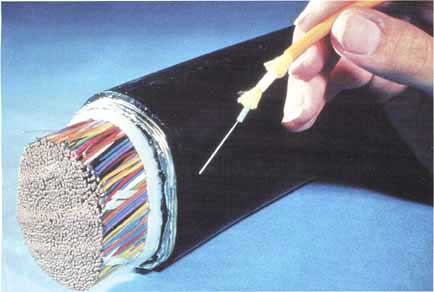
Outside plant cables often have very high fiber counts, up to 288 fibers or more. Cable designs are optimized for the application: cables in conduit for pulling tension and resisting moisture, buried cables for resisting moisture and rodent damage, aerial for continuous tension and extreme weather and undersea for resisting moisture penetration. Installation requires special equipment like pullers or plows, and even trailers to carry giant spools of cable.
Long distances mean cables are spliced together, since cables are not manufactured in lengths longer than about 45 km (2.-3 miles), and most splices are by fusion splicing. Connectors (generally SC or LC styles) on factory made pigtails are spliced onto the end of the cable. After installation, every fiber and every splice is tested with an OTDR.
If this sounds expensive, you are right! The installer usually has a temperature controlled van or trailer for splicing and/or a bucket truck. Investments in fusion splicers, OTDRs and other equipment can be quite expensive.
Most outside plant telephone installs are done by the telco themselves, while a small number of large, specialized installers do CATV, utility and municipal work.
Telephone companies, CATV and the Internet all use lots of fiber optics, virtually all of which is singlemode fiber and most of which is outside buildings. It hangs from poles, is buried underground, pulled through conduit or is even submerged underwater. Most of it goes relatively long distances, from a few hundred feet to hundreds of miles.
Outside plant cables often have very high fiber counts, up to 288 fibers or more. Cable designs are optimized for the application: cables in conduit for pulling tension and resisting moisture, buried cables for resisting moisture and rodent damage, aerial for continuous tension and extreme weather and undersea for resisting moisture penetration. Installation requires special equipment like pullers or plows, and even trailers to carry giant spools of cable.
Long distances mean cables are spliced together, since cables are not manufactured in lengths longer than about 45 km (2.-3 miles), and most splices are by fusion splicing. Connectors (generally SC or LC styles) on factory made pigtails are spliced onto the end of the cable. After installation, every fiber and every splice is tested with an OTDR.
If this sounds expensive, you are right! The installer usually has a temperature controlled van or trailer for splicing and/or a bucket truck. Investments in fusion splicers, OTDRs and other equipment can be quite expensive.
Most outside plant telephone installs are done by the telco themselves, while a small number of large, specialized installers do CATV, utility and municipal work.
Premises Cabling
 By contrast, premises cabling- cabling installed in a building
or campus - involves shorter lengths, rarely longer than a few
hundred feet, typically with fewer fibers per cable. The fiber
is mostly multimode, except for the enlightened user who installs
hybrid cable with both multimode and singlemode fibers for future high bandwidth applications.
By contrast, premises cabling- cabling installed in a building
or campus - involves shorter lengths, rarely longer than a few
hundred feet, typically with fewer fibers per cable. The fiber
is mostly multimode, except for the enlightened user who installs
hybrid cable with both multimode and singlemode fibers for future high bandwidth applications.
Splicing is practically unknown in premises applications. Cables between buildings can be bought with double jackets, PE for outside plant protection over PVC for building applications requiring flame retardant cable jackets, so cables can be run continuously between buildings. Today's connectors often have lower loss than splices, and patch panels give more flexibility for moves, adds and changes.
Most connectors are SC or ST style with LCs becoming more popular. Termination is by installing connectors directly on the ends of the fibers, primarily using adhesive or sometimes prepolished splice techniques. Testing is done by a source and meter, but every installer should have a flashlight type tracer to check fiber continuity and connection.
Unlike the outside plant technician, the premises cable installer (who is often also installing the power cable and Cat 5/6 for LANs too!) probably has an investment of less than $2,000 in tools and test equipment.
There are thousands of cabling installers who do fiber optic work. They've found out it isn't "rocket science," and their small initial investment in training, tools and test equipment is rapidly paid back.
Few installers do both outside plant and premises cabling. The companies that do are usually very large and often have separate divisions doing each with different personnel. Most contractors do nothing but premises cabling.
By contrast, premises cabling- cabling installed in a building
or campus - involves shorter lengths, rarely longer than a few
hundred feet, typically with fewer fibers per cable. The fiber
is mostly multimode, except for the enlightened user who installs
hybrid cable with both multimode and singlemode fibers for future high bandwidth applications.Splicing is practically unknown in premises applications. Cables between buildings can be bought with double jackets, PE for outside plant protection over PVC for building applications requiring flame retardant cable jackets, so cables can be run continuously between buildings. Today's connectors often have lower loss than splices, and patch panels give more flexibility for moves, adds and changes.
Most connectors are SC or ST style with LCs becoming more popular. Termination is by installing connectors directly on the ends of the fibers, primarily using adhesive or sometimes prepolished splice techniques. Testing is done by a source and meter, but every installer should have a flashlight type tracer to check fiber continuity and connection.
Unlike the outside plant technician, the premises cable installer (who is often also installing the power cable and Cat 5/6 for LANs too!) probably has an investment of less than $2,000 in tools and test equipment.
There are thousands of cabling installers who do fiber optic work. They've found out it isn't "rocket science," and their small initial investment in training, tools and test equipment is rapidly paid back.
Few installers do both outside plant and premises cabling. The companies that do are usually very large and often have separate divisions doing each with different personnel. Most contractors do nothing but premises cabling.
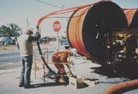
- The biggest advantage of optical fiber is the fact it is the most cost effective means of transporting information. Fiber can transport more information longer distances in less time than any other communications medium, as the photo on the left from the late 1970s illustrates so well.
- The bandwidth and distance capability of fiber means that fewer cables are needed, fewer repeaters, less power and less maintenance. In addition, fiber is unaffected by the interference of electromagnetic radiation which makes it possible to transmit information and data with less noise and less error. Fiber is lighter than copper wires which makes it popular for aircraft and automotive applications.
Wireless
was used as a long distance medium until fiber became available, but
wireless is limited by available transmission frequencies so it was
dropped as a long distance medium. While local wireless has grown
exponentially, it uses fiber as a backbone and connection to the
international phone system and Internet.
- These advantages makes the use of optical fiber the most logical choice in data transmission.
- Twenty
five years ago, fiber was just being introduced. It was expensive and
required PhD's from Bell Labs to install it while copper wire was easy
to install. Today most communications installers do fiber and wireless as well as copper.
Because fiber is so powerful, at today's network speeds fiber still has plenty of headroom and users can look to the future of ten to one hundred gigabit speeds with confidence. Telcos use DSL over copper today but it's very limited in bandwidth over typical subscriber connection lengths and many older copper wires will not support DSL speeds, leading to the adoption of fiber to the home. Copper gigabit Ethernet can work over short cables in LANs or but only if it is carefully installed and tested. - But isn't fiber more expensive? Telcos and CATV operators use fiber because it's actually much cheaper. They optimize the architecture of their network to take advantage of fiber's speed and distance advantages. In LANs, you need to follow the EIA/TIA 568 standard for "centralized fiber" to optimize the fiber usage, and then it can be cheaper than copper. Installing the proper fiber today in a LAN will give you good chance of being able to handle new network speeds for years to come. One fiber, FDDI grade 62.5/125, outlasted 9 generations of copper! See Networks for more information on how to use fiber.
- The Secret To Success In Fiber
Optics Is Training!
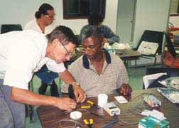
You wouldn't try to drive a truck or fly a plane without taking lessons. Likewise for improving your golf or tennis game. Well, the secret to fiber optics is training too. With some basic knowledge and hands-on practice gained in a training course, fiber is pretty easy to install.
Where to Get Training?
Well, you can start right here at the FOA, of course! This reference guide is
designed to get you started and you should have "hands-on" training
leading to a recognized certification program like the FOA CFOT to be
qualified to install fiber. Check the website
of the Fiber Optic Association at http://www.TheFOA.org.
for the leading fiber optic certification program in the industry.
Finally, take advantage of the training offered by manufacturers
and distributors whenever you can, often this training is free
or cheap! (but limited to the manufacturer's equipment
of course.)
- How about Certification?
- That's what the FOA is all about. We have hundreds of FOA-approved schools offering FOA certifications. Over 30,000 students have been certified by FOA schools (7/2010.)Around the world, FOA is recognized as the leader in fiber optic education and certification.
- Standards
- The
adoption of any technology depends on having workable standards
to insure product compatibility. Most of what we call standards are
voluntary standards created by industry groups. Standards are not
"codes" or actual laws that you must follow to be in compliance with
local ordinances but sensible guidelines to ensure proper operation of
communications systems. Standards are often developed by groups within
each country, like EIA/TIA or IEEE in the US, but are increasingly
becoming international under the auspices of ISO and IEC.
Standards like EIA/TIA 568 ( from the Electronic Industries Alliance/ Telecommunications Industry Association in the US) which covers all of the things you need to know to install a standard premises cabling network are good guidelines for designs and should be followed to ensure interoperability.
Primary measurement standards like for optical power measurements are set by standards organizations in each country like NIST (the US National Institute of Standards and Technology) and coordinated worldwide.
The only common "mandatory standard" in the US - we call them codes - is the NEC 770 (National Electrical Code). The NEC specifies fire prevention standards for fiber optic cables. Other countries have similar codes for building safety. If an indoor cable doesn't have a NEC rating - don't install it - it won't pass inspection! - A listing of the EIA/TIA standards is on the website of The Fiber Optic Association. Information on the EIA/TIA standards can be found on the website of most of the suppliers of structured cabling hardware.
.
You
might think that eye damage from working with lasers would be the big
concern in fiber optic installations. The reality is that high power
lasers burning holes in metal or burning off warts mostly have little
relevance to your typical fiber optic installation. Optical sources
used in fiber optics are generally of much lower power levels (The
exception is high power DWDM or CATV systems). Of course, you should
always be careful with your eyes, especially when using a fiber optic
microscope which can concentrate all the light from the fiber into your
eye. NEVER look into a fiber unless you know no light is present - use
a power meter to check it - and anyway, the light is in the infrared
and you can't see anything anyway!
The real safety lecture will
always be about small scraps of glass cleaved off the ends of
the fibers being terminated or spliced. These scraps are very
dangerous! The cleaved ends are extremely sharp and can easily
penetrate your skin. If they get into your eyes, they are very
hard to flush out. Don't even think about what happens if you
eat one. Always wear safety glasses whenever working with fiber and always carefully dispose of all fiber scraps!
Always follow these rules when
working with fiber.
1. Always wear safety glasses to protect your eyes from fiber scraps.
2. Dispose of all scraps properly. Always use a properly marked container to dispose of later and work on a black pad which makes the slivers of glass easier to spot.
3. Do not drop them on the floor where they will stick in carpets or shoes and be carried elsewhere.
4. Do not eat or drink anywhere near the work area.
Fiber
optic splicing and termination use various chemical adhesives and
cleaners as part of the processes. Follow the instructions for use
(detailed on the chemical's MSDS - material safety data sheet)
carefully. Remember, even simple isopropyl alcohol, used as a cleaner,
is flammable.
.
Zero Tolerance for Dirt
With fiber optics, our tolerance
to dirt is near zero. Airborne particles are about the size of
the core of SM fiber- they absorb lots of light and may scratch
connectors if not removed! Dirt on connectors is the biggest
cause of scratches on polished connectors and high loss measurements!
1. Try to work in a clean area.
Avoid working around heating outlets, as they blow dust all over
you
2. Always keep dust caps on connectors, bulkhead splices, patch panels or anything else that is going to have a connection made with it.
3. Use special fiber optic cleaners or lint free pads and isopropyl alcohol to clean the connectors.
4. Ferrules on the connectors/cables used for testing will get dirty by scraping off the material of the alignment sleeve in the splice bushing - creating an attenuator. You can see the front edge of the connector ferrule getting black! Use the metal or ceramic alignment sleeve bulkheads only for testing.
Fiber Optic Jargon
The
key to understanding any technology is understanding the language of
the technology – the jargon. We’ve started this book with an overview
of fiber jargon to introduce you to the language of fiber optics and
help you understand what you will be reading in the book. While we try
to use the most common terminology, some particular applications for
optical fiber have their own specialized terms, and when possible, we
will try to include those terms also. We suggest you read this section
first to help your understanding of the rest of the book and refer back
to it when you encounter a term that you do not recognize. You can also
use the definitions in the Glossary or the FOA Online Reference Guide for more explanations.
What is fiber optics?
Fiber optics is sending signals from one location to another in the form of modulated light guided
through hair-thin fibers of glass or plastic. These signals can be
analog or digital and voice, data or video information. Fiber
can transport more information longer distances in less time
than any copper wire or wireless method.
It's powerful and very
fast - offering more bandwidth than any other form of communication!
First you need to know the language
- the "jargon" - here's a list of terms you should
know:
The Metric System
- Fiber Optics, as an international technology, utilizes the metric system as the standard form of measurement.
- Several of the more common terms:
- Meter: 3.28 feet, 39.37 inches. Fiber optic cable lengths are generally expressed in meters or kilometers.
Kilometer: 1000 meters / 3,281 feet / 0.62 miles.
Micron: 1/1,000,000 th of a meter. 25 microns equal 0.001 inch. This is the common term of measurement for fiber diameters, most of which are 125 microns in outside diameter.
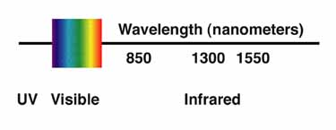
Nanometer: One billionth of one meter. This term is commonly used in the fiber optics industry to express wavelength of transmitted light, e.g 850 or 1300 nm.
Optical Fiber: Thin strands of highly transparent glass
or
plastic that guide light.
plastic that guide light.
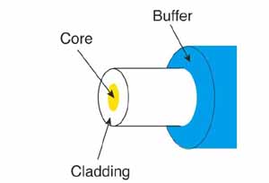
Core: The center of the fiber where the light is transmitted.
Cladding: The outside optical layer of the fiber
that traps the light in the core and guides it along - even through
curves.
Buffer coating or primary
buffer coating: A hard plastic
coating on the outside of the fiber that protects the glass from
moisture or physical damage. The buffer is what one strips off the fiber for termination or splicing.
Mode: A single "electromagnetic field pattern" (think
of a ray of light) that travels in fiber.
Multimode fiber: has a larger core (almost always 50 or 62.5
microns - a micron is one one millionth of a meter) and is used with laser or LED sources at wavelengths of 850
and 1300 nm for short distance, lower speed data networks like LANs.
Singlemode fiber:
has a much smaller core, only about 8-9 microns, so it only transmits one
mode. Singlemode is used for telephony (long distance, metropolitan and
fiber to the home) and CATV with laser sources at 1310 to 1550 nm. It
can go very long distances at very high speeds.
Fiber ID: Fibers
are identified by their core and cladding diameters expressed in
microns (one millionth of a meter), e.g. 50/125 micron multimode fiber. Most
multimode and singlemode fibers have an outside diameter of 125 microns
- about 0.005 - 5 thousandths of an inch - just slightly larger than a
human hair. International standards also have names for fibers that
call out detailed specifications that include bandwidth capability or other special characteristics.
Plastic optical fiber (POF): is a large core (usually 1mm) multimode
fiber that can be used for short, low speed networks. POF is
used in consumer HiFi and as part of a
standard for car communication systems called MOST (go to http://www.mostcooperation.com/) More on POF.
Cable:
Cable provides protection to the fiber from stress during installation
and from the environment once it is installed. Cables may contain from
only one to hundreds of fibers inside. Cables come in three varieties:
tight buffer with a thick plastic coating on the fibers for protection,
used mainly indoors, loose-tube, where fibers with only a primary
buffer coating are inside plastic tubes, and ribbon, where fibers are
made into ribbons to allow small cables with the largest numbers of
fibers.
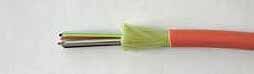
Jacket: The tough outer covering on the cable. Cables installed inside buildings must meet fire codes by using special jacketing materials.
Strength members: Aramid fibers (Kevlar is the duPont
trade name) used to pull the cable. The term is also used for
the fiberglass rod in some cables used to stiffen it to prevent
kinking.
Armor: Prevents
crushing and discourages rodents from damaging cable by chewing through
it. Some cable called armored also includes layers of strengthening
wires for use in extreme environments such as encountered by submarine
cables.
Sheath: A term used for the combination of the jacket, armor and any other elements used to protect the fibers in a cable.
Sheath: A term used for the combination of the jacket, armor and any other elements used to protect the fibers in a cable.
Outside Plant InstallationsOutside plant installations fall into four general categories, depending on the placement of the cable. Each requires cable types chosen for the installation and specialized equipment for placement.
Underground: Cables placed underground in conduit, often inside innerduct pulled in the conduit. Cables can also be blown into duct lines installed by trenching or plowing.
Direct Buried: Cable placed underground without conduit, placed in trenches, plowed into the ground or installed by directional boring.
Aerial: Cable placed above ground on utility poles.
Submarine: Cables placed underwater, including those in shallow water such as lakes or rivers as well as those used for ocean crossings.
Connector: A non-permanent device for connecting
two fibers in a non-permanent joint or connect fibers to equipment. Connectors are expected
to be disconnected occasionally for testing or rerouting. (Parts for an ST connector
are shown.)
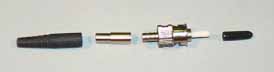
Ferrule: A tube which holds a fiber for alignment, usually part of a connector
Splice: a permanent joint between two fibers
Mechanical Splice: A splice where the fibers are aligned
created by mechanical means
Fusion Splice: A splice created by welding or fusing
two fibers together
Fusion Splicer: An instrument that splices fibers by
fusing or welding them, typically by electrical arc.
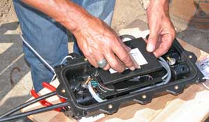
Hardware: Terminations and Splices require hardware for
protection and management: patch panels, splice closures (shown below), etc.
Terms you use when you want to specity fibers or make measurements of fiber optic components or cable plants:
Attenuation:
The reduction in optical power as it passes along a fiber, usually
expressed in decibels (dB). For fibers, we talk about attenuation
coefficient or attenuation per unit length, in dB/km. See optical loss
Bandwidth: The range of signal frequencies or
bit rate within which a fiber optic component, link or network
will operate.
Decibels (dB): A unit of measurement of optical power
which indicates relative power. A -10 dB means a reduction in
power by 10 times, -20 dB means another 10 times or 100 times
overall, -30 means another 10 times or 1000 times overall and
so on.
dB: Optical power referenced an arbitrary zero level, used to measure loss
dBm: Optical power referenced to 1 milliwatt, used to measure optical power from transmitters or at receivers. See optical power.
Optical Loss: The amount of optical power lost as
light is transmitted through fiber, splices, couplers, etc, expressed
in "dB."
Optical Power: is measured in "dBm", or decibels
referenced to one miliwatt of power. while loss is a relative
reading, optical power is an absolute measurement, referenced
to standards. You measure absolute power to test transmitters
or receivers and relative power to test loss.
Dispersion: Pulse spreading caused by modes in multimode fiber (modal dispersion), the difference in speed of light of different wavelengths (CD or chromatic dispersion in multimode or singlemode fiber ) or polarization (PMD or polarization mode dispersion in singlemode)
Dispersion: Pulse spreading caused by modes in multimode fiber (modal dispersion), the difference in speed of light of different wavelengths (CD or chromatic dispersion in multimode or singlemode fiber ) or polarization (PMD or polarization mode dispersion in singlemode)
Scattering: The change of direction of light after
striking small particles that causes the majority of loss in optical fibers and
is used to make measurements by an OTDR
Wavelength: A term for the color of light, usually
expressed in nanometers (nm) or microns (m). Fiber is mostly
used in the infrared region where the light is invisible to the
human eye. Most fiber specifications (attenuation, dispersion) are dependent on wavelength.
Dispersion:
Pulse spreading caused by modes in multimode fiber (modal dispersion), the difference in
speed of light of different wavelengths (CD or chromatic dispersion in multimode or singlemode fiber ) and
polarization (PMD or polarization mode dispersion in singlemode)
Terms that describe the tools needed for installation and termination:
Jacket Slitter or Stripper: A cutter for removing the heavy outside
jacket of cables
Fiber Stripper: A precise stripper used to remove the
buffer coating of the fiber itself for termination. There at
three types in common use, called by their trade names: "Miller
Stripper", "No-Nik" and "Micro Strip."
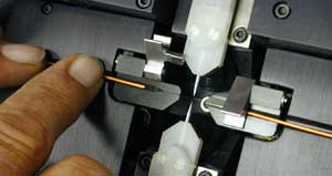
Cleaver: A tool that precisely "breaks"
the fiber to produce a flat end for polishing or splicing.
Scribe: A hard, sharp tool that scratches the fiber to allow cleaving.
Polishing Puck: for connectors that require polishing,
the puck holds the connector in proper alignment to the polishing
film.
Polishing Film: Fine grit film used to polish the end
of the connector ferrule.
Crimper: A tool that crimps the connector to the aramid
fibers in the cable to add mechanical strength.
Fusion Splicer: An instrument that welds two fibers together into a permanent joint.
Terms that describe fiber optic test equipment:
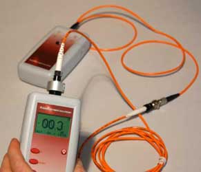
Optical Power Meter: An instrument that measures optical
power from the end of a fiber
Test Source: an instrument that uses a laser or
LED to send an optical signal into fiber for testing loss of
the fiber
Optical Loss Test Set (OLTS):
A measurement instrument that includes both a meter and source used for
measuring insertion loss of installed cable plants or individual cables. ALso called light source and power meter (LSPM.)
Reference Test Cables: short, single fiber cables with connectors
on both ends, used to test unknown cables.
Mating Adapter: also called splice bushing or couplers,
allow two cables with connectors to mate.
Fiber Tracer: An visible light source (LED or flashlight) that allows visual checking
of continuity and tracing for correct connections such as duplex connector polarity
Visual Fault Locator: A high-powered visible laser light source that allows continuity testing, fiber tracing and location of faults near the end of the cable.
Inspection Microscope: used to inspect the end surface of
a connector for faults such as scratches, polish or dirt.
Optical Time Domain Reflectometer (OTDR):
An instrument that uses backscattered light to take a snapshot of an
optical fiber which can be used to measure fiber length, splice loss,
fiber attenuation and for fault location in optical fiber from only one
end of the cable.
Specialized Testers: Long
distance networks may need testing for chromatic dispersion (CD) and
polarization mode dispersion (PMD). Systems using wavelength-division
multiplexing may need testing for spectral attenuation. Each
performance factor has a specialized tester for that specification.
Fiber In Communications
- Jump to:
Internet
- Telephone
CATV
- Security
Utility
Metropolitan
Premises
Fiber
has become the communications medium of choice for telephones, cell
phones, CATV, LAN backbones, security cameras, industrial networks,
just about everything.
Why use fiber?
The
biggest advantage of optical fiber is the fact it is the most cost
effective means of transporting information. FIber can transport more
information longer distances in less time than any other
communications medium, as the photo on the left from the late 1970s
illustrates so well. The bandwidth and distance capability of fiber
means that fewer cables are needed, fewer repeaters, less power and
less maintenance. In addition, fiber is unaffected by the interference
of electromagnetic radiation which makes it possible to transmit
information and data with less noise and less error. Fiber is lighter
than copper wires which makes it popular for aircraft and automotive
applications. These advantages open up the doors for many other
advantages that make the use of optical fiber the most logical choice
in data transmission.
These
advantages have led to fiber becoming the transport medium of choice
for practically all data, voice and video communications.
Both
telcos and CATV operators use fiber for economic reasons, but their
cost justification requires adopting new network architectures to take
advantage of fiber's strengths. LAN and premises network designers and
installers now realize that they must also adopt new network
architectures too. A properly designed premises cabling network can
also be less expensive when done in fiber instead of copper. Conversion
from copper networks is easy with media converters, gadgets that
convert most types of systems to fiber optics. Even adding the cost of
the media converters, the fiber optic network will usually be less than
copper when the proper architecture is used.
Fiber Optic Communication Networks
Outside Plant Networks
Telephone Networks
Telephone networks were the first major users of fiber optics. Fiber optic links were used to replace copper or digital radio links between telephone switches, beginning with long distance links, called long lines, where fiber's distance and bandwidth capabilities made fiber significantly more cost effective. Telcos use fiber to connect all their central offices and long distance switches because it has thousands of times the bandwidth of copper wire and can carry signals hundreds of times further before needing a repeater - making the cost of a phone connection over fiber only a few percent of the cost of the same connection on copper.
After
long distance links were converted to fiber, telcos began replacing
shorter links between switches with fiber, for example between switches
in the same metropolitan area. Today, with the exception of some rugged
or remote locations, the entire telephone backbone is fiber optics.
Cables on the land are run underground, direct buried or aerially,
depending on the geography and local regulations. Connections around
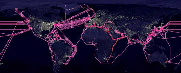
the world are run primarily on undersea cables which now link every
continent and most island nations with the exception of Antarctica.
After
long distance links were converted to fiber, telcos began replacing
shorter links between switches with fiber, for example between switches
in the same metropolitan area. Today, practically all the telephone
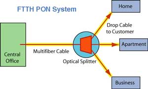
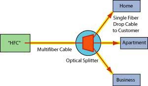
networks have been converted to fiber. Telcos and other groups are now
running fiber right to the home, (FTTH) using low cost passive optical
network (PON) systems that use splitters to share the cost of some
fiber optic components among as many as 32 subscribers. More on FTTH, FTTH PON types and FTTH network architecture.
Even
cell phone networks have fiber
backbones. It's more efficient and less expensive than using precious
wireless bandwidth for backbone connections. Cell phone towers with
many antennas will have large cable trays or pedestals where fiber
cables connect to the antenna electronics.
The Internet
The Internet
The
Internet has always been based on a fiber optic backbone. It started as
part of the telephone network when it was primarily voice and data
traffic was mixed into the total traffic. But data has
become the largest communications network as data traffic has outgrown
voice traffic. The Internet now transmits user communications, e.g.
requesting and downloading web pages or email, peer-to-peer
transmissions, streaming video and massive data transfers between data
centers. Large Internet providers are moving toward dedicated Internet
networks that do not have the high overhead of telco networks which are
burdened with transporting dozens of different types of communications
services still being supported by the telco system providers. Now the
telcos are moving their voice communications to
Internet protocol (IP) for lower costs.
CATVMost CATV systems are using fiber backbones too. CATV companies use fiber because it give them greater reliability and the opportunity to offer new services, like phone service and Internet connections.
CATV used to have a terrible reputation for reliability, not really a problem with service but with network topology. CATV uses very high frequency analog signals, up to 1 GHz, which has high attenuation over coax cable. For a city-wide system, CATV needed many amplifiers (repeaters) to reach the users at the end of the system; 15 or more we common. Amplifiers failed often, meaning that subscriber downstream of the failed amp lost signal. Finding and fixing failed amps was difficult and time consuming, causing subscriber complaints.
The
development of highly linear distributed feedback (DFB) lasers allowed
CATV systems to be converted to analog optical systems.
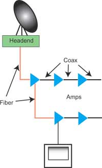
CATV companies "overbuild" with fiber. They connect their headends with
fiber and then take fiber into the neighborhood. They lash the fiber
cable onto the aerial "hardline" coax used for the rest of the network
or pull it in the same conduit underground. The fiber allows them to
break their network into smaller service areas, typically fewer than 4 amplifiers deep, that prevent large
numbers of customers from being affected in an outage, making their network more
reliable and easier to troubleshoot, providing better service and
customer relations.
The fiber also gives CATV operators a return path which they use for Internet and telephone connections, increasing their revenue potential. Most current CATV systems still use AM (analog) systems which simply convert the electrical TV signals into optical signals. Look for them to convert to more digital transmission in the future.
The fiber also gives CATV operators a return path which they use for Internet and telephone connections, increasing their revenue potential. Most current CATV systems still use AM (analog) systems which simply convert the electrical TV signals into optical signals. Look for them to convert to more digital transmission in the future.
CATV is even developing its own version of fiber to the home called RF over glass (RFOG.) This uses a interface at the home that is like a cable modem but with an optical input that accepts the same analog radio frequency (RF) signals that are used throughout the HFC network.
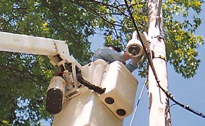
Security systems can have a wider reach and are more secure on fiber. Practically any system today has a fiber optic option. CCTV cameras used for surveillance often use fiber for it's distance capability and security, especially in large buildings like airports and around cities with metropolitan networks. Fiber also has much more bandwidth than coax so several cameras can be multiplexed onto one fiber. Bidirectional links allow controlling pan, zoom and tilt (PZT) cameras. Other security devices like intrusion alarms or perimeter alarms can utilize fiber and some even use fiber optic sensors.
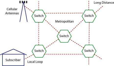
Metropolitan Networks
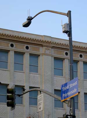
Many cities have incorporated fiber optics into their communications networks. Metropolitan networks use fiber for many other applications besides CCTV surveillance cameras, including connecting public service agencies such as fire, police and other emergency services, hospitals, schools, as well as connecting municipal WiFi and traffic management systems as shown in the photo. Cities can install cables to strategic locations so various services can share the fibers in the cables, saving installation costs. Cities are also learning to bury extra conduits every time a roadway is dug up so when cables need installing, no further construction is needed.
Utility Networks
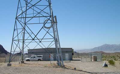
Utilities use fiber for communications, CCTV surveillance and network management. Electrical utilities have used fiber optics for decades for communications and managing their distribution systems. They realized quickly that fiber’s immunity to electromagnetic interference would allow them to operate communications and control networks in close proximity to electrical circuits without problems. Electrical utilities take full advantage of fiber's immunity to noise also, even running fiber inside high voltage power distribution cables. Some utilities install fibers inside their high voltage distribution networks using optical power ground wire (OPGW) and lease fibers to other telecommunications companies. Utilities use fiber in one non-communications application; fiber optic sensors allow monitoring high voltage and current in their distribution systems. The interest in "smart grid" management of power distribution to enhance efficiency is based on using fiber optics for network management.
Premises Networks
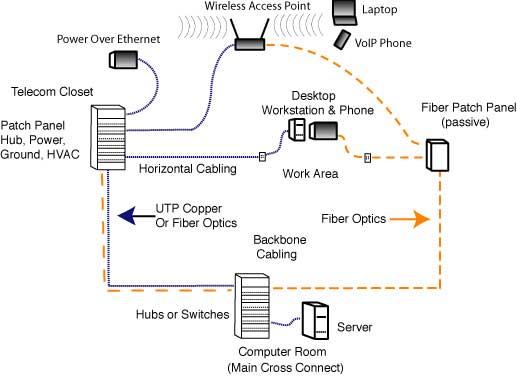
Premises networks, mostly computer LANs (local area networks) use fiber optics primarily in the backbone but increasingly to the desk and to connect wireless access points. The LAN backbone often needs longer distances than copper cable (Cat 5/5e/6/6A) can provide and of course, the fiber offers higher bandwidth for future expansion. Fiber's ability to handle network upgrades meant that one fiber type outlived nine generations of copper cables in LANs. A new fiber type (OM3) offers future potential for upgrades while copper continues to struggle with network speed increases.
Until recently large corporate LANs use fiber backbones with copper wire to the desktop. LAN switches and hubs are usually available with fiber optic ports but PCs have interfaces to Ethernet on copper. Inexpensive media converters allow connecting PCs to fiber. Fiber to the desk can be cost effective if properly designed using centralized fiber architecture without local switching in the telecom closet, but many users no longer want to be "tethered" to a network cable. Desktop computer sales are declining and laptops are the PC of choice for most users, with wireless connections to the network. Generally only high data users like engineers and graphics designers use desktop workstations; everybody else gets a wireless-connected laptop.
Centralized Fiber LANs
- When most contractors and end users look at fiber optics versus Category-rated UTP cabling for a LAN, they compare the same old copper LAN with fiber directly replacing the copper links. The installed cost of a fiber optic cable plant comparable to the cost of Cat 5/6/6A, but fiber often requires medial conversion electronics which add cost to the link for fiber.
- However, the real difference comes if you use a centralized fiber optic network - shown on the right of the diagram above. Since fiber does not have the 90 meter distance limitation of UTP cable, you can place all electronics in one location in or near the computer room. The telecom room is only used for passive connection of backbone fiber optic cables, so no power, UPS, ground or air conditioning is needed. These auxiliary services, necessary with Cat 5 hubs, cost a tremendous amount of money in each telecom room. If designing a new building, you do not even need the cost of the telecom room itself.
- In addition, having all the fiber optic hubs in one location means better utilization of the hardware, with fewer unused ports. Since ports in modular hubs must be added in modules of 8 or 16, it's not uncommon with a hub in a telecom closet to have many of the ports in a module empty . With a centralized fiber system, you can add modules more efficiently as you are supporting many more desktop locations but need never have more than a one module with open ports.
Industrial Networks
Industrial plants use fiber for it's ruggedness, distance and noise immunity. In an industrial environment, electromagnetic interference (EMI) is often a big problem. Motors, relays, welders and other industrial equipment generate a tremendous amount of electrical noise that can cause major problems with copper cabling, especially unshielded cable like UTP. In order to run copper cable in an industrial environment, it is often necessary to pull it through conduit to provide adequate shielding. Fiber is also very flexible, so many industrial robots use fiber for controls, often plastic fiber.
Fiber optics has complete immunity to EMI. You only need to choose a cable type that is rugged enough for the installation, with breakout cable being a good choice for it's heavy-duty construction. The fiber optic cable can be installed easily from point to point, passing right next to major sources of EMI with no effect. Conversion from copper networks is easy with media converters, gadgets that convert most types of systems to fiber optics. Even with the cost of the media converters, the fiber optic network will be less than copper run in conduit.
- Military and Platforms
- The military uses fiber everywhere, on bases, platforms (ships and planes), and on the battlefield because it's hard to damage, tap or jam. Airplanes use fiber for its reliability and noise immunity, but also like the lighter weight of fiber. Even millions of cars have fiber networks connecting all the electronics because fiber is immune to noise and saves weight.
Fiber Optic Links
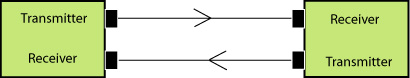 Fiber
optic links work by sending optical signals over fiber. Fiber optic
transmission systems all use data links that work similar to the
diagram shown above. Each fiber link consists of a transmitter on one
end of a fiber and a receiver on the other end. Most systems operate by
transmitting in one direction on one fiber and in the reverse direction
on another fiber for full duplex operation. Transmitters are
semiconductor LEDs or lasers and receivers are semiconductor
photodetectors.
Fiber
optic links work by sending optical signals over fiber. Fiber optic
transmission systems all use data links that work similar to the
diagram shown above. Each fiber link consists of a transmitter on one
end of a fiber and a receiver on the other end. Most systems operate by
transmitting in one direction on one fiber and in the reverse direction
on another fiber for full duplex operation. Transmitters are
semiconductor LEDs or lasers and receivers are semiconductor
photodetectors. For more information on fiber optic links, see the next section on Transmission Systems.
Designing Fiber Optic Networks
This
is a big topic so we have a complete section
on the subject of Design.
Fiber's extra bandwidth and distance capability makes it possible to do things
not possible with copper wire or wireless.
First and foremost, it's necessary to understand thoroughly what
signals are to
be transmitted over the fiber and the specifications of the
transmission equipment. Then map and visit the work site to understand
where the fiber optic cable plant needs to be installed. Know
the standards but use common sense in designing the
installation. Consider what are the possible problems and work around or
prevent them. Don't cut corners which may affect performance or
reliability. Document everything completely. Plan for future expansion
and restoration in case of problems. There is no substitute for
experience and common sense here!
OSP Fiber Optic Transmission Systems

Fiber Optic Datalink
Fiber Optic Datalink
Fiber optic transmission systems all use data links that work similar to the diagram shown above. Each fiber link consists of a transmitter on one end of a fiber and a receiver on the other end. Most systems operate by transmitting in one direction on one fiber and in the reverse direction on another fiber for full duplex operation. It's possible to transmit both directions on one fiber but it requires couplers to do so and fiber is less expensive than couplers. A FTTH passive optical network (PON) is one of the only systems using bidirectional transmission over a single fiber because its network architecture is based around couplers already.
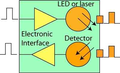
Fiber Optic Transceiver
Most systems use a "transceiver" which includes both transmission and receiver in a single module. The transmitter takes an electrical input and converts it to an optical output from a laser diode or LED. The light from the transmitter is coupled into the fiber with a connector and is transmitted through the fiber optic cable plant. The light from the end of the fiber is coupled to a receiver where a detector converts the light into an electrical signal which is then conditioned properly for use by the receiving equipment.
Analog or Digital
Analog
signals are continuously variable signals where the information in the
signal is contained in the amplitude of the signal over time. Digital
signals are sampled at regular time intervals and the amplitude
converted to digital bytes so the information is a digital number.
Analog signals are the natural form of most data, but are subject to
degradation by noise in the transmission system. As an analog signal is
attenuated in a cable, the signal to noise ratio becomes worse so the
quality of the signal degrades. Digital signals can be transmitted long
distances without degradation as the signal is less sensitive to noise.
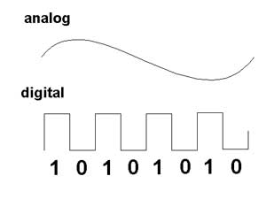
Fiber optic datalinks can be either analog or digital in nature, although most are digital. Both have
some common critical parameters and some major differences. For
both, the optical loss margin or power budget is most important. This is determined
by connecting the link up with an adjustable attenuator in the
cable plant and varying the loss between transmitter and receiver until one can generate the curve
shown above. Analog datalinks will be tested for signal to noise
ratio to determine link margin, while digital links use bit error
rate as a measure of performance. Both links require testing over
the full bandwidth specified for operation, but most data links
are now specified for a specific network application, like AM
CATV or RGB color monitors for analog links and SONET, Ethernet or Fibre Channel for digital links.
The
sources used for fiber optic transmitters need to meet several
criteria: it has to be at the correct wavelength, be able to be
modulated fast enough to transmit data and be efficiently coupled into
fiber.
Four types of sources are commonly
used, LEDs, fabry-perot (FP) lasers, distributed feedback (DFB) lasers and vertical cavity surface-emitting
lasers (VCSELs). All convert electrical signals into optical
signals, but are otherwise quite different devices. All three are tiny
semiconductor devices (chips). LEDs and VCSELs are fabricated on
semiconductor wafers such that they emit light from the surface of the
chip, while f-p lasers emit from the side of the chip from a laser
cavity created in the middle of the chip.
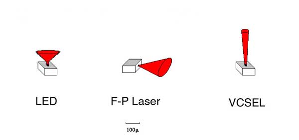
LEDs
have much lower power outputs than lasers and their
larger, diverging light output pattern makes them harder to couple
into fibers, limiting them to use with multimode fibers. Laser have
smaller tighter light outputs and are easily coupled to singlemode
fibers, making them ideal for long distance high speed links. LEDs have
much less bandwidth than lasers and are limited to systems operating up
to about 250 MHz or around 200 Mb/s. Lasers have very high bandwidth
capability, most being useful to well over 10 GHz or 10 Gb/s.
Because of their fabrication methods, LEDs and VCSELs are cheap to make. Lasers are more expensive because creating the laser cavity inside the device is more difficult, the chip must be separated from the semiconductor wafer and each end coated before the laser can even be tested to see if its good.Typical Fiber Optic Source Specifications
Because of their fabrication methods, LEDs and VCSELs are cheap to make. Lasers are more expensive because creating the laser cavity inside the device is more difficult, the chip must be separated from the semiconductor wafer and each end coated before the laser can even be tested to see if its good.Typical Fiber Optic Source Specifications
| Device Type | Wavelength (nm) | Power into Fiber (dBm) | Bandwidth | Fiber Types |
| LED | 850, 1300 | -30 to -10 | <250 MHz | MM |
| Fabry-Perot Laser | 850, 1310 (1280-1330) 1550 (1480-1650) | 0 to +10 | >10 GHz | MM, SM |
| DFB Laser | 1550 (1480-1650) | 0 to +25 | >10 GHz | SM |
| VCSEL | 850 | -10 to 0 | >10 GHz | MM |
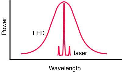
LEDs
have a limited bandwidth while all types of lasers are very fast.
Another big difference between LEDs and both types of lasers is the
spectral output. LEDs have a very broad spectral output which causes
them to suffer chromatic dispersion in fiber, while lasers have a
narrow spectral output that suffers very little chromatic dispersion. DFB lasers, which are used in long distance and DWDM systems, have the narrowest spectral width which minimizes chromatic dispersion on the longest links. DFB lasers are also
highly linear (that is the light output directly follows the electrical
input) so they can be used as sources in AM CATV systems.
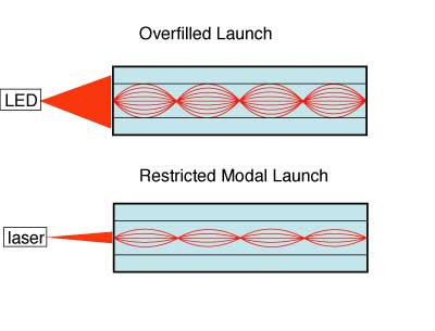
The choice of these devices is determined mainly by speed and fiber compatibility issues. As many premises systems using multimode fiber have exceeded bit rates of 1 Gb/s, lasers (mostly VCSELs) have replaced LEDs. The output of the LED is very broad but lasers are very focused, and the sources will have very different modal fill in the fibers. The restricted launch of the VCSEL (or any laser) makes the effective bandwidth of the fiber higher, but laser-optimized fiber, usually OM3, is the choice for lasers.
The
electronics for a transmitter are simple. They convert an incoming
pulse (voltage) into a precise current pulse to drive the source.
Lasers generally are biased with a low DC current and modulated above
that bias current to maximize speed.
Receivers
use semiconductor detectors (photodiodes or photodetectors) to convert
optical signals to electrical signals. Silicon photodiodes
are used for short wavelength links (650 for POF and 850 for glass MM
fiber). Long wavelength systems usually use InGaAs (indium gallium
arsenide) detectors as they have lower noise than germanium which
allows for more sensitive receivers.
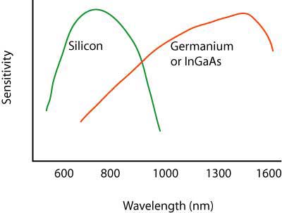
Very high speed systems sometimes use avalanche photodiodes (APDs) that are biased at high voltage to create gain in the photodiode. These devices are more expensive and more complicated to use but offer significant gains in performance.
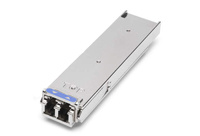
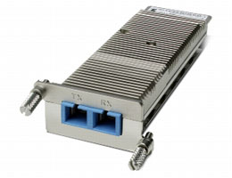
Packaging
Transcivers
are usually packaged in industry standard packages like these XFP
modules for gigabit datalinks(L) and Xenpak (R). The XFP modules
connect to a duplex LC connector on the optical end and a standard
electrical interface on the other end. The Xenpak are for 10 gigabit
networks but use SC duplex connection. Both are similar to media converters but are powered from the equipment they are built into.
Performance
Just
as with copper
wire or radio transmission, the performance of the fiber optic
data link can be determined by how well the reconverted electrical
signal out of the receiver matches the input to the transmitter.
The discussion of performance on datalinks applies directly to
transceivers which supply the optical to electrical conversion.
Every
manufacturer of transcivers specifies
their product for receiver sensitivity (perhaps a minimum power
required)
and minimum power coupled into the fiber from the source. Those
specifications will end up being the datalink specifications on the
final product used in the field.
Why Is WDM Used?
With the exponential growth in communications, caused mainly by the wide acceptance of the Internet, many carriers are finding that their estimates of fiber needs have been highly underestimated. Although most cables included many spare fibers when installed, this growth has used many of them and new capacity is needed. Three methods exist for expanding capacity: 1) installing more cables, 2) increasing system bitrate to multiplex more signals or 3) wavelength division multiplexing.
Installing more cables will be the preferred method in many cases, especially in metropolitan areas, since fiber has become incredibly inexpensive and installation methods more efficient (like mass fusion splicing.) But if conduit space is not available or major construction is necessary, this may not be the most cost effective.
Increasing system bitrate may not prove cost effective either. Many systems are already running at SONET OC-48 rates (2.5 GB/s) and upgrading to OC-192 (10 GB/s) is expensive, requires changing out all the electronics in a network, and adds 4 times the capacity, more than may be necessary.
The third alternative, wavelength division multiplexing (WDM), has proven more cost effective in many instances. It allows using current electronics and current fibers, but simply shares fibers by transmitting different channels at different wavelengths (colors) of light. Systems that already use fiber optic amplifiers as repeaters also do not require upgrading for most WDM systems.
How Does WDM Work?
It is easy to understand WDM. Consider the fact that you can see many different colors of light - reg, green, yellow, blue, etc. all at once. The colors are transmitted through the air together and may mix, but they can be easily separated using a simple device like a prism, just like we separate the "white" light from the sun into a spectrum of colors with the prism.
It is easy to understand WDM. Consider the fact that you can see many different colors of light - reg, green, yellow, blue, etc. all at once. The colors are transmitted through the air together and may mix, but they can be easily separated using a simple device like a prism, just like we separate the "white" light from the sun into a spectrum of colors with the prism.
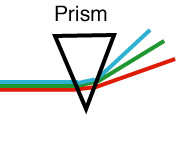
Separating a beam of
light into
its colors
This technique was first
demonstrated with
optical fiber in the early 80s when telco fiber optic links still
used multimode fiber. Light at 850 nm and 1300 nm was injected
into the fiber at one end using a simple fused coupler. At the
far end of the fiber, another coupler split the light into two
fibers, one sent to a silicon detector more sensitive to 850 nm
and one to a germanium or InGaAs detector more sensitive to 1300
nm. Filters removed the unwanted wavelengths, so each detector
then was able to receive only the signal intended for it.
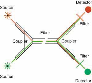
WDM with couplers
and filters
By the late 80s, all telecom
links were
singlemode fiber, and coupler manufactures learned how to make
fused couplers that could separate 1300nm and 1550 nm signals
adequately to allow WDM with simple, inexpensive components. However,
these had limited usefulness, as fiber was designed differently
for 1300nm and 1550 nm, due to the dispersion characteristics
of glass. Fiber optimized at 1300 nm was used for local loop links,
while long haul and submarine cables used dispersion-shifted fiber
optimized for performance at 1550 nm. This simple version of WDM is
widely used in fiber to the home (FTTH) applications. Signals are sent
downstream to the subscriber at 1490 nm (and 1550 for analog CATV if
used) and upstream at 1310 n.
With the advent of fiber optic amplifiers for repeaters in the late 80s (see below), emphasis shifted to the 1550 nm transmission band. WDM only made sense if the multiplexed wavelengths were in the region of the fiber amplifiers operating range of 1520 to 1560 nm. It was not long before WDM equipment was able to put 4 signals into this band, with wavelengths about 10 nm apart.
The input end of a WDM system is really quite simple. It is a simple coupler that combines all the inputs into one output fiber. These have been available for many years, offering 2, 4, 8, 16, 32 or even 64 inputs. It is the demultiplexer that is the difficult component to make.
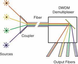
WDM demultiplexer
The demultiplexer takes the
input fiber
and collimates the light into a narrow, parallel beam of light.
It shines on a grating (a mirror like device that works like a
prism, similar to the data side of a CD) which separates the light
into the different wavelengths by sending them off at different
angles. Optics capture each wavelength and focuses it into a fiber,
creating separate outputs for each separate wavelength of light.
DWDM
Current systems offer from 4 to 32 channels of wavelengths. The higher numbers of wavelengths has lead to the name Dense Wavelength Division Multiplexing or DWDM. The technical requirement is only that the lasers be of very specific wavelengths and the wavelengths are very stable, and the DWDM demultiplexers capable of distinguishing each wavelength without crosstalk.
Current systems offer from 4 to 32 channels of wavelengths. The higher numbers of wavelengths has lead to the name Dense Wavelength Division Multiplexing or DWDM. The technical requirement is only that the lasers be of very specific wavelengths and the wavelengths are very stable, and the DWDM demultiplexers capable of distinguishing each wavelength without crosstalk.
CWDM
Coarse wavelength-division multiplexing is another variant of WDM. Generally CWDM refers to using lasers spaced 20 nm apart over the full range of 1260 to 1670 nm. It only works on low water peak fibers, where the high water absorption bands have been eliminated in the manufacture of the fiber.
Coarse wavelength-division multiplexing is another variant of WDM. Generally CWDM refers to using lasers spaced 20 nm apart over the full range of 1260 to 1670 nm. It only works on low water peak fibers, where the high water absorption bands have been eliminated in the manufacture of the fiber.
Advantages of WDM
A WDM system has some features that make them very useable. Each wavelength can be from a normal link, for example a OC-48 link, so you do not obsolete most of your current equipment. You merely need laser transmitterss chosen for wavelengths that match the WDM demultiplexer to make sure each channel is properly decoded at the receiving end.
If you use an OC-48 SONET input, you can have 4X2.5 GB/s = 10 GB/s up to 32 X 2.5 GB/s = 80 GB/s. While 32 channels are the maximum today, future enhancements are expected to offer 80-128 channels!
And you are not limited to SONET, you can use Gigabit Ethernet for example, or you can mix and match SONET and Gigabit Ethernet or any other digital signals! You can even mix in analog channels like CATV, as is done with BPON FTTH systems.
Repeaters
Another technology that facilitates DWDM is the development of fiber optic amplifiers for use as repeaters. They can amplify numerous wavelengths of light simultaneously, as long as all are in the wavelength range of the FO amplifier. They work best in the range of 1520-1560 nm, so most DWDM systems are designed for that range. Now that fiber has been made with less effect from the OH absorption bands at 1400 nm and 1600 nm, the possible range of DWDM has broadened considerably. Technology needs development for wider range fiber amplifiers to take advantage of the new fibers.
Another technology that facilitates DWDM is the development of fiber optic amplifiers for use as repeaters. They can amplify numerous wavelengths of light simultaneously, as long as all are in the wavelength range of the FO amplifier. They work best in the range of 1520-1560 nm, so most DWDM systems are designed for that range. Now that fiber has been made with less effect from the OH absorption bands at 1400 nm and 1600 nm, the possible range of DWDM has broadened considerably. Technology needs development for wider range fiber amplifiers to take advantage of the new fibers.
Fiber
Amplifiers
While the low loss of optical
fiber allows
signals to travel hundreds of kilometers, extremely long haul
lines and submarine cables require regenerators or repeaters to
amplify the signal periodically. In the beginning, repeaters basically
consisted of a receiver followed by a transmitter. The incoming
signal was converted from a light signal to an electrical signal
by a receiver, cleaned up to remove as much noise as possible,
then was retransmitted by another laser transmitter.
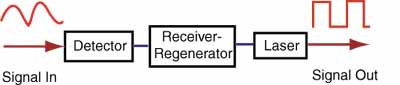
Electronic Repeater
These repeaters added noise to
the signal,
consumed much power and were complicated, which means they were
a source of failure. They also had to be made for the specific
bit rate of transmission and upgrading required replacing all
the repeaters, a really difficult task in an undersea cable!
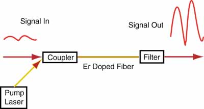
Since the 1960s, researchers knew how to make fiber lasers. Proper doping of the fiber (introducing small amounts of active elements into the glass fiber) allowed it to be pumped with external light sources until stimulated emission occurred. While making fiber amplifiers was hypothesized early in the stages of fiber optic development, it was not until 1987 that working models were realized. Major contributors to the development included Bell Labs and NTT.
The typical fiber amplifier works in the 1550 nm band and consists of a length of fiber doped with Erbium pumped with a laser at 980. The pump laser supplies the energy for the amplifier, while the incoming signal stimulates emission as the pulse passes through the doped fiber. The stimulated emission stimulates more emission, so there is a rapid, exponential growth of photons in the doped fiber. Gains of >40 dB (10,000X) are possible with power outputs >+20 dBm (100 mW).
Basic Fiber Amplifier
To date, the most efficient
fiber amplifiers
have been Erbium-Doped Fiber Amplifiers (EDFAs) operating in the
1550 nm range. Since most systems still work at 1310 nm, considerable
research has been done to find materials that would work in this
range. Praseodymium-doped fluoride fiber amplifiers (PDFFAs) using
fibers made from zirconium fluoride or hafnium fluoride have shown
some promise, but have not developed the performance needed for
widespread applications.
The basic structure of an EDFA is very simple. The amplifier itself emits light energy in a signal wavelength (usually about 1540nm) using energy supplied to it by photons in a pump wavelength (usually 980nm) when stimulated by incoming photons in the signal - the signal which needs amplification. Just like in a laser, the emitted photons then stimulate other emissions, so there is an exponential growth of photons. Supporting the amplifier is a pump laser, which supplies the amplifier's energy, a coupler, which combines the pump laser beams and the signal laser beam and puts them on a single fiber, and an optical filter, which removes the remaining traces of the pump beam so that it doesn't interfere with reception of the signal.
The basic structure of an EDFA is very simple. The amplifier itself emits light energy in a signal wavelength (usually about 1540nm) using energy supplied to it by photons in a pump wavelength (usually 980nm) when stimulated by incoming photons in the signal - the signal which needs amplification. Just like in a laser, the emitted photons then stimulate other emissions, so there is an exponential growth of photons. Supporting the amplifier is a pump laser, which supplies the amplifier's energy, a coupler, which combines the pump laser beams and the signal laser beam and puts them on a single fiber, and an optical filter, which removes the remaining traces of the pump beam so that it doesn't interfere with reception of the signal.
Alternative Designs
The simple diagram of an EDFA shown above is not the only way EDFAs can be made. Pumping can be done in a forward direction as shown, backward from the output end or in both directions. Optical isolators are commonly used at both ends of the EDFA to prevent pump energy from escaping back down the fiber or unwanted reflections that may affect laser stability. Filters, often Bragg gratings (filters fabricated in fibers), are used to flatten the gain over the broadest wavelength range for use in WDM systems.
The simple diagram of an EDFA shown above is not the only way EDFAs can be made. Pumping can be done in a forward direction as shown, backward from the output end or in both directions. Optical isolators are commonly used at both ends of the EDFA to prevent pump energy from escaping back down the fiber or unwanted reflections that may affect laser stability. Filters, often Bragg gratings (filters fabricated in fibers), are used to flatten the gain over the broadest wavelength range for use in WDM systems.
- Other Applications
- Besides being used as repeaters, fiber amplifiers are used to increase signal level for CATV systems, which require high power levels at the receiver to maintain adequate signal to noise performance, allowing longer cable runs or using splitters to "broadcast" a single signal through a coupler to many fibers, saving the cost of additional transmitters. In telephony, they combine with DWDM (dense wavelength division multiplexers) to overcome the inefficiencies of DWDMs for long haul transmission.
Future Developments
Fiber amplifiers continue to be developed to support Dense Wavelength Division Multiplexing and to expand to the other wavelength bands supported by fiber optics. Now that fiber manufacturers have all but removed the water bands from the spectrum, there is now a range of 1260 to 1610 nm available for use. Fiber amplifiers and diode lasers will probably be developed within this band to completely fill it with useable bandwidth.
Fiber amplifiers continue to be developed to support Dense Wavelength Division Multiplexing and to expand to the other wavelength bands supported by fiber optics. Now that fiber manufacturers have all but removed the water bands from the spectrum, there is now a range of 1260 to 1610 nm available for use. Fiber amplifiers and diode lasers will probably be developed within this band to completely fill it with useable bandwidth.
Applications
Two obvious applications are already in use, submarine cables and extending the lifetime of cables where all fibers are being used. For submarine cables, DWDM enhances the capacity without adding fibers, which create larger cables and bulkier and more complicated repeaters. Adding service in areas where cables are now full is another good application.
But this technology may also reduce the cost on all land-based long distance communications links and new technology may lead to totally new network architectures.
Further Enhancements
Imagine an all-optical network that uses DWDM, switches signals in the optical domain without converting signals to electronics, and can add or drop signals by inserting or withdrawing wavelengths at will. All this is being researched right now, and given the speed with which optical technology advances, an all-optical network may not be far in the future!
Imagine an all-optical network that uses DWDM, switches signals in the optical domain without converting signals to electronics, and can add or drop signals by inserting or withdrawing wavelengths at will. All this is being researched right now, and given the speed with which optical technology advances, an all-optical network may not be far in the future!
Fiber Optic Network Optical Wavelength Transmission Bands
As
fiber optic networks have developed for longer distances, higher speeds
and wavelength-division multiplexing (WDM), fibers have been used in
new wavelength ranges, now called "bands," where fiber and transmission
equipment can operate more efficiently. Singlemode fiber transmission
began in the "O-band" just above the cutoff wavelength of the SM fiber
developed to take advantage of the lower loss of the glass fiber at
longer wavelengths and availablility of 1310 nm diode lasers.
(Originally SM fibers were developed for 850 nm lasers where the fiber
core was about half what it is for today's conventional SM fiber (5
microns as opposed to 8-9 microns at 1310 nm.)
To take advantage of the lower loss at 1550 nm, fiber was developed for the C-band. As links became longer and fiber amplifiers began being used instead of optical-to-electronic-to-optical repeaters, the C-band became more important. With the advent of DWDM (dense wavelength-division multiplexing) which allowed multiple signals to share a single fiber, use of this band was expanded. Development of new fiber amplifiers (Raman and thullium-doped) promise to expand DWDM upward to the L-band.
Since the fiber manufacturers have been able to reduce the water peaks at 1244 and 1383 nm to very low levels, several low-cost versions of WDM are in use, generally referred to as Coarse WDM or CWDM. Most do not work over long distances so do not require amplification, broading the wavelength choice. The most popular is FTTH PON systems, sending signals downstream to users at 1490 nm and using low cost 1310 nm transmission upstream. Early PON systems also use 1550 downstream for TV, but that is being replaced by IPTV on the downstream digital signal at 1490 nm. Other systems use a combination of S, C and L bands to carry signals because of the lower attenuation of the fiber. Some systems even use lasers at 20 nm spacings over the complete range of 1260 to 1660 nm but only with low water peak fibers.
Manufacturers have been able to make fiber with low-water peaks, opening up a new transmission band (E-band), but it has not yet proven useful except for CWDM. It is probably mostly useful as an extension of the O-band but few applications have been proposed and it is very energy-intensive for manufacture.
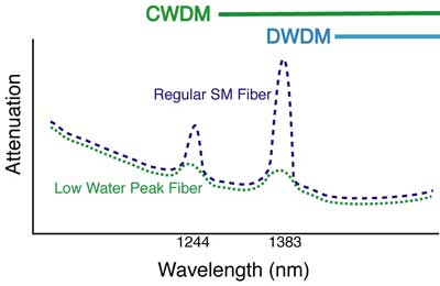
Low Water Peak Fiber
Wavelength Bands Used For Fiber Optic Transmission Systems
| Band Name | Wavelengths | Description |
| O-band | 1260 – 1360 nm | Original band, PON upstream, low end of CWDM systems |
| E-band | 1360 – 1460 nm | Water peak band |
| S-band | 1460 – 1530 nm | PON downstream |
| C-band | 1530 – 1565 nm | Lowest attenuation, original DWDM band, compatible with fiber amplifiers, CATV |
| L-band | 1565 – 1625 nm | Low attenuation, expanded DWDM band |
| U-band | 1625 – 1675 nm | |
Just as with copper
wire or radio transmission, the performance of the fiber optic
data link can be determined by how well the reconverted electrical
signal out of the receiver matches the input to the transmitter.
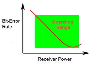
The ability of any fiber optic system to
transmit data ultimately
depends on the optical power at the receiver as shown above, which
shows the data link bit error rate as a function of optical power
at the receiver. (BER is the inverse of signal-to-noise ratio, e.g.
high BER means poor signal to noise ratio.) Either too little or
too much power will cause
high bit error rates. Too much power, and the receiver amplifier
saturates, too little and noise becomes a problem as it interferes with
the signal. This receiver
power depends on two basic factors: how much power is launched
into the fiber by the transmitter and how much is lost by attenuation
in the optical fiber cable plant that connects the transmitter and
receiver.
The optical power budget of the link is determined by two factors,
the sensitivity of the receiver, which is determined in the bit
error rate curve above and the output power of the transmitter
into the fiber. The minimum power level that produces an acceptable
bit error rate determines the sensitivity the receiver. The power
from the transmitter coupled into the optical fiber determines
the transmitted power. The difference between these two power
levels determines the loss margin (power budget) of the link.
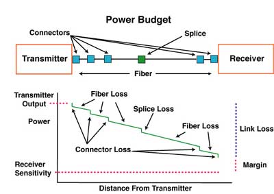
High speed
links like gigabit or 10gigabit Ethernet LANs on multimode fiber have
derating factors for the bandwidth of fiber caused by dispersion spreading out the data pulse. Older 62.5/125 OM1 fiber
will generally operate only on shorter links while links on 50/125 OM3
laser-optimized fiber will go the longest distance. Even long distance
singlemode fiber links may have limitations caused by chromatic or
polarization-mode dispersion.
If the link is
designed to operate at differing bit rates, it is necessary to
generate the performance curve for each bit-rate. Since the total
power in the signal is a function of pulse width and pulse width
will vary with bit-rate (higher bit-rates means shorter pulses),
the receiver sensitivity will degrade at higher bit-rates.Every manufacturer of datalinks components and systems specifies
their link for receiver sensitivity (perhaps a minimum power required)
and minimum power coupled into the fiber from the source. Typical
values for these parameters are shown in the table below. In order for a manufacturer or system designer to
test them properly, it is necessary to know the test conditions.
For data link components, that includes input data frequency or bitrate
and duty cycle, power supply voltages and the type of fiber coupled
to the source. For systems, it will be the diagnostic software
needed by the system.
Typical Fiber optic link/system performance parameters
| Link type | Source/Fiber Type |
Wave- length (nm) | Transmit Power (dBm) | Receiver Sen- sitivity (dBm) | Margin (dB) |
| Telecom | laser/SM | 1300/1550 | +3 to -6 | -30 to -45 | 30 to 40 |
| DWDM | 1550 | +20 to 0 | -30 to -45 | 40 to 50 | |
| Datacom | LED/VCSEL | 850 | -3 to -15 | -15 to -30 | 3 to 25 |
| LED/laser | 1300 | -0 to -20 | -15 to -30 | 10 to 25 | |
| CATV(AM) | laser/SM | 1300/1550 | +10 to 0 | 0 to -10 | 10 to 20 |
Within the world of datacommunications links and networks, there are
many vendor-specific fiber optic systems, but there are also a
number of industry standard networks such as Ethernet which have fiber optic standards. These networks have agreed
upon specifications common to all manufacturers' products to insure
interoperability. This page in FOA Tech Topics shows a summary of specifications for many of these systems.
Long Distance ConsiderationsFiber
optic links can now be hundreds or even thousands of kilometers long
and operate at 10 gigabits per second or more – certainly lots more in
the future – and at many wavelengths over a single fiber. Problems that
are ignorable on short or metropolitan links may become extremely
important on long links. The section on optical fiber
will cover topics like chromatic dispersion, polarization mode
dispersion and spectral attenuation that can be important in these long
links.
Summary
Datalinks must have proper receiver power, neither too little
nor too much, for proper operation.
The link margin can be measured with a power meter and variable
attenuator.
Fiber Optic Cable
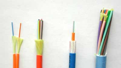
Cable Types: (L>R): Zipcord, Distribution,
Loose Tube, Breakout
Cable provides protection for the optical fiber or fibers within it appropriate for the environment in which it is installed.
Fiber
optic "cable" refers to the complete assembly of fibers, strength
members and jacket. Fiber optic cables come in lots of different types,
depending on the number of fibers and how and where it will be
installed. It is important to choose cable carefully as the choice will
affect how easy the cable is to install, splice or terminate and what
it will cost.
Cable's
job is to protect the fibers from the environment encountered in an
installation. Outdoors, it depends on whether the cable is buried
directly, pulled in conduit, strung aerially or even placed underwater.
Will the cable become wet or moist? Will it have to withstand high
pulling tension for installation in conduit or continual tension in an
aerial installation? Will the cable be exposed to chemicals or have to
withstand a wide temperature range? What about being gnawed on by a
squirrel, woodchuck or prairie dog? Indoors, cables don't have to be so
strong to protect the fibers, but they have to meet all fire code
provisions so the cable jacket has to be flame-retardant,
Outside plant cable designs are optimized for the application type. In OSP installations, cables may be underground, direct buried, aerial or submarine (or simply underwater.)
Outside plant cable designs are optimized for the application type. In OSP installations, cables may be underground, direct buried, aerial or submarine (or simply underwater.)
Underground Cables
Underground cables are generally installed in conduit which is usually a 4 inch (10 cm) conduit with several innerducts for pulling cables. Here cables are designed for high pulling tension and lubricants are used to reduce friction on longer pulls. Automated pulling equipment that limits pulling tension protects the cables. Very long runs or those with more bends in the conduit may need intermediate pulls where cable is pulled, figure-8ed and then pulled to the next stage or intermediate pulling equipment is used. An alternative is to install duct lines and blow special lightweight cables into the ducts which can be faster and less stressful on the cable.
Splices on underground cables are generally stored above ground in a pedestal or in a vault underground. Sufficient excess cable is needed to allow splicing in a controlled environment, usually a splicing trailer, and the storage of excess cable must be considered in the planning stage.
Direct Buried Cable
Direct buried cable is placed underground without conduit. Here the cable must be designed to withstand the rigors of being buried in dirt, so it is generally a more rugged cable, armored to prevent harm from rodent chewing or the pressures of dirt and rocks in which it is buried. Direct burial is generally limited to areas where the ground is mostly soil with few rocks down to the depth required so trenching or plowing in cable is easily accomplished. Splices on direct buried cables can be stored above ground in a pedestal or buried underground. Sufficient excess cable is needed to allow splicing in a controlled environment, usually a splicing trailer, and the storage of excess cable must be considered.
Direct buried cable is placed underground without conduit. Here the cable must be designed to withstand the rigors of being buried in dirt, so it is generally a more rugged cable, armored to prevent harm from rodent chewing or the pressures of dirt and rocks in which it is buried. Direct burial is generally limited to areas where the ground is mostly soil with few rocks down to the depth required so trenching or plowing in cable is easily accomplished. Splices on direct buried cables can be stored above ground in a pedestal or buried underground. Sufficient excess cable is needed to allow splicing in a controlled environment, usually a splicing trailer, and the storage of excess cable must be considered.
Aerial Cable
Aerial installations go from pole to pole, but the method of securing cables can vary depending on the situation. Some cables are lashed to messengers or other cables, such as CATV where light fiber cables are often lashed to the heavy coax already in place. Cables are available in a “8” configuration with an attached steel messenger that provides the strength to withstand tension on the cable. Some cables are made to directly be supported without a messenger, called all-dielectric self-supporting cables that use special hardware on poles to hold the cables. Optical ground wire is used by utilities for high voltage distribution lines. This cable is an electrical cable with fibers in the middle in a hermetically-sealed metal tube. It is installed just like standard electrical conductors. Splices on aerial cables can be supported on the cables or placed on poles or towers, Most splices are done on the ground, although it is sometimes done in a bucket or even on a tent supported on the pole or tower. Hardware is available for coiling and storing excess cable.
Aerial installations go from pole to pole, but the method of securing cables can vary depending on the situation. Some cables are lashed to messengers or other cables, such as CATV where light fiber cables are often lashed to the heavy coax already in place. Cables are available in a “8” configuration with an attached steel messenger that provides the strength to withstand tension on the cable. Some cables are made to directly be supported without a messenger, called all-dielectric self-supporting cables that use special hardware on poles to hold the cables. Optical ground wire is used by utilities for high voltage distribution lines. This cable is an electrical cable with fibers in the middle in a hermetically-sealed metal tube. It is installed just like standard electrical conductors. Splices on aerial cables can be supported on the cables or placed on poles or towers, Most splices are done on the ground, although it is sometimes done in a bucket or even on a tent supported on the pole or tower. Hardware is available for coiling and storing excess cable.
Submarine/Underwater Cables
Sometime OSP installations involve running cables across rivers or lakes where other routes are not possible. Special cables are available for this that are more rugged and sealed. Even underwater splice hardware is available. Landings on the shore need to be planned to prevent damage, generally by burying the cable close to shore and marking the landing. Transoceanic links are similar but much more complex, requiring special ships designed for cable laying.
Sometime OSP installations involve running cables across rivers or lakes where other routes are not possible. Special cables are available for this that are more rugged and sealed. Even underwater splice hardware is available. Landings on the shore need to be planned to prevent damage, generally by burying the cable close to shore and marking the landing. Transoceanic links are similar but much more complex, requiring special ships designed for cable laying.
Since
OSP applications often use significant lengths of cables, the cables
can be made to order, allowing optimization for that particular
installation. This usually allows saving costs but requires more
knowledge on the part of the user and more time to negotiate with
several cable manufacturers.
- Fiber Optic Cable Construction
- All cables are comprised of layers of protection for the fibers. Most all start with standard fiber with a primary buffer coating (250 microns) and add:
Tight buffer coating
(tight buffer cables like simplex, zipcord, distribution and breakout
types): A soft protective coating applied directly to the 250 micron
coated fiber to provide additional protection for the fiber, allowing
easier handling, even direct termination on the fiber.
Loose Tubes (loose
tube cables): Small, thin plastic tubes containing as many as a dozen
250 micron buffered fibers used to protect fibers in cables rated for
outside plant use. They allow the fibers to be isolated from high
pulling tension and can be filled with water-blocking materials to
prevent moisture entry.
Strength members:
Strength members are usually aramid yarn, the same used in bulletproof
vests, often called by the Dupont trade name Kevlar, which absorbs the
tension needed to pull the cable and provides cushioning for the
fibers. Aramid fibers are used not only because they are strong, but
they do not stretch. If pulled hard, they will not stretch but
eventually break when tension exceeds their limits. This ensures that
the strength members will not stretch and then relax, binding the
fibers in the cable. The proper method of pulling fiber optic cables is
always to attach the pull rope, wire or tape to the strength members.
Some cables also include a central fiberglass rod used for additional strength and to stiffen the cable to prevent kinking and damaging the fibers. When included, these rods should be attached to swivel pulling eyes for pulling and clamps in splice closures or patch panels when spliced or terminated. Few cables today use metallic strength members since it complicates installation by requiring the cable to be properly grounded and bonded.
Some cables also include a central fiberglass rod used for additional strength and to stiffen the cable to prevent kinking and damaging the fibers. When included, these rods should be attached to swivel pulling eyes for pulling and clamps in splice closures or patch panels when spliced or terminated. Few cables today use metallic strength members since it complicates installation by requiring the cable to be properly grounded and bonded.
Cable Jacket: The
outermost layer of protection for the fibers which is chosen to
withstand the environment in which the cable is installed. Outdoor
cables will generally be black polyethylene (PE) which resists moisture
and sunlight exposure. Indoor cables use flame-retardant jackets that
can be color-coded to identify the fibers inside the cable. Some
outdoor cables may have double jackets with a tough layer of
armor between them to protect from chewing by rodents or Kevlar for
strength to allow pulling by the jackets.
Indoor cables usually have a flame-retardant PVC (polyvinyl chloride) jacket for general or riser use and some other special plastic for plenum use in air handling areas. Indoor-outdoor cables usually have a PE outer jacket that can be removed to expose a flame-retardant inner jacket for use within buildings.
Protection Against Water and Moisture
Cables installed outdoors require protecting the fibers from water. Either a gel or as is becoming more common, absorbent tape or powder, is used to prevent water from entering the cable and causing harm to the fibers. Generally, this applies to loose tube or ribbon cables, but dry water-blocking is used on some tight buffer cables used in short outdoor runs, such as building to building on a campus or to an outdoor wireless antenna or CCTV camera.
Protection Against Crushing or Rodent Penetration
Some cables have armor, usually metallic but sometimes hard plastic, under the outer jacket resist crushing loads, such as cables installed under floors in data centers or in rocky soil, as well as to prevent rodent penetration. Metallic armor requires that the cable be properly grounded and bonded.
Look at the pictures below to see how each type of cable incorporates these components.
- Fiber Optic Cable Types
Tight Buffer Cable Types
There are two basic types of cables, generally defined as tight buffer and loose tube. Tight buffer cables (simplex, zipcord, distribution and breakout) are primarily used in premises applications where cable flexibility and ease of termination are important, more so than ruggedness, weather sealing and pulling strength which characterize loose tube and ribbon types of cable. Generally, tight buffer cables are used indoors and loose tube/ribbon cables outdoors, but some tight buffer cables with moisture protection are used in short runs like on a campus or between buildings.
Simplex and zip cord
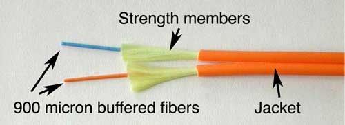
These types are used mostly for patch cord and backplane applications, but zipcord can also be used for desktop connections. Simplex cables are one fiber, tight-buffered (coated with a 900 micron buffer over the primary buffer coating) with Kevlar (aramid fiber) strength members and jacketed for indoor use. The jacket is usually 3mm (1/8 in.) diameter, but some 2 mm cable is sometimes used with small form factor connectors. Zipcord is simply two of these joined with a thin web.
These types are used mostly for patch cord and backplane applications, but zipcord can also be used for desktop connections. Simplex cables are one fiber, tight-buffered (coated with a 900 micron buffer over the primary buffer coating) with Kevlar (aramid fiber) strength members and jacketed for indoor use. The jacket is usually 3mm (1/8 in.) diameter, but some 2 mm cable is sometimes used with small form factor connectors. Zipcord is simply two of these joined with a thin web.
Distribution cables:
 Distribution cable is the most popular indoor cable, as it is small in
size and light in weight. They contain several tight-buffered fibers
bundled under the same jacket with Kevlar strength members and
sometimes fiberglass rod reinforcement to stiffen the cable and prevent
kinking. These cables are small in size, and used for short, dry
conduit runs, riser and plenum applications. The fibers are double
buffered and can be directly terminated, but because their fibers are
not individually reinforced, these cables need to be broken out with a
"breakout box" or terminated inside a patch panel or junction box to protect individual fibers.
Distribution cable is the most popular indoor cable, as it is small in
size and light in weight. They contain several tight-buffered fibers
bundled under the same jacket with Kevlar strength members and
sometimes fiberglass rod reinforcement to stiffen the cable and prevent
kinking. These cables are small in size, and used for short, dry
conduit runs, riser and plenum applications. The fibers are double
buffered and can be directly terminated, but because their fibers are
not individually reinforced, these cables need to be broken out with a
"breakout box" or terminated inside a patch panel or junction box to protect individual fibers.
Breakout cables:
Breakout cable is a favorite where rugged cables are desirable or direct termination without junction boxes, patch panels or other hardware is needed. They are made of several simplex cables bundled together insdie a common jacket. This is a strong, rugged design, but is larger and more expensive than the distribution cables. It is suitable for conduit runs, riser and plenum applications. It's perfect for industrial applications where ruggedness is needed. Because each fiber is individually reinforced, this design allows for quick termination to connectors and does not require patch panels or boxes. Breakout cable can be more economic where fiber count isn't too large and distances too long, because is requires so much less labor to terminate.
Breakout cable is a favorite where rugged cables are desirable or direct termination without junction boxes, patch panels or other hardware is needed. They are made of several simplex cables bundled together insdie a common jacket. This is a strong, rugged design, but is larger and more expensive than the distribution cables. It is suitable for conduit runs, riser and plenum applications. It's perfect for industrial applications where ruggedness is needed. Because each fiber is individually reinforced, this design allows for quick termination to connectors and does not require patch panels or boxes. Breakout cable can be more economic where fiber count isn't too large and distances too long, because is requires so much less labor to terminate.
Loose tube cables:
 Loose
tube cables are the most widely used cables for outside plant
trunks because it
offers the best protection for the fibers under high pulling tensions
and can be easily protected from moisture with water-blocking gel or
tapes.These cables are composed of
several fibers together inside a small plastic tube, which are in turn
wound around a central strength member, surrounded by aramid strength
members and jacketed, providing a small,
high fiber count cable. This type of cable is ideal for outside plant
trunking applications, as it can be made with the loose tubes filled
with gel or water absorbent powder to prevent harm to the fibers from
water. It can be used in conduits, strung overhead or buried directly
into the ground. Some outdoor cables may have
double jackets with a metallic armor between them to protect from
chewing by rodents or kevlar for strength to allow pulling by the
jackets.
Since the fibers have only a thin buffer coating, they
must be carefully handled and protected to prevent damage. Loose tube
cables with singlemode fibers are generally terminated by spicing
pigtails onto the fibers and protecting them in a splice closure.
Multimode loose tube cables can be terminated directly by installing a
breakout kit, also called a furcation or fan-out kit, which sleeves
each fiber for protection.
Loose
tube cables are the most widely used cables for outside plant
trunks because it
offers the best protection for the fibers under high pulling tensions
and can be easily protected from moisture with water-blocking gel or
tapes.These cables are composed of
several fibers together inside a small plastic tube, which are in turn
wound around a central strength member, surrounded by aramid strength
members and jacketed, providing a small,
high fiber count cable. This type of cable is ideal for outside plant
trunking applications, as it can be made with the loose tubes filled
with gel or water absorbent powder to prevent harm to the fibers from
water. It can be used in conduits, strung overhead or buried directly
into the ground. Some outdoor cables may have
double jackets with a metallic armor between them to protect from
chewing by rodents or kevlar for strength to allow pulling by the
jackets.
Since the fibers have only a thin buffer coating, they
must be carefully handled and protected to prevent damage. Loose tube
cables with singlemode fibers are generally terminated by spicing
pigtails onto the fibers and protecting them in a splice closure.
Multimode loose tube cables can be terminated directly by installing a
breakout kit, also called a furcation or fan-out kit, which sleeves
each fiber for protection.
Ribbon Cable:
Ribbon cable is preferred where high fiber counts and small diameter cables are needed. This cable has the most fibers in the smallest cable, since all the fibers are laid out in rows in ribbons, typically of 12 fibers, and the ribbons are laid on top of each other. Not only is this the smallest cable for the most number of fibers, it's usually the lowest cost. Typically 144 fibers in ribbons only has a cross section of about 1/4 inch or 6 mm and the jacket is only 13 mm or 1/2 inch diameter! Some cable designs use a "slotted core" with up to 6 of these 144 fiber ribbon assemblies for 864 fibers in one cable! Since it's outside plant cable, it's gel-filled for water blocking or dry water-blocked. Another advantage of ribbon cable is Mass Fusion Splicers can join a ribbon (12 fibers) at once, making installation fast and easy. Ribbon pigtails are spliced onto the cable for quick termination. Premises cabling also uses some ribbon cables, often in preterminated cabling systems where 12 fibers are terminated in one MTP connector. These cables are common in LAN backbones and data centers.
Ribbon cable is preferred where high fiber counts and small diameter cables are needed. This cable has the most fibers in the smallest cable, since all the fibers are laid out in rows in ribbons, typically of 12 fibers, and the ribbons are laid on top of each other. Not only is this the smallest cable for the most number of fibers, it's usually the lowest cost. Typically 144 fibers in ribbons only has a cross section of about 1/4 inch or 6 mm and the jacket is only 13 mm or 1/2 inch diameter! Some cable designs use a "slotted core" with up to 6 of these 144 fiber ribbon assemblies for 864 fibers in one cable! Since it's outside plant cable, it's gel-filled for water blocking or dry water-blocked. Another advantage of ribbon cable is Mass Fusion Splicers can join a ribbon (12 fibers) at once, making installation fast and easy. Ribbon pigtails are spliced onto the cable for quick termination. Premises cabling also uses some ribbon cables, often in preterminated cabling systems where 12 fibers are terminated in one MTP connector. These cables are common in LAN backbones and data centers.
Armored Cable:
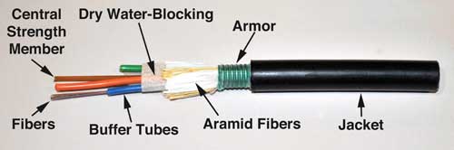
Armored cable is used in direct buried outside plant applications where a rugged cable is needed and/or for rodent resistance. Armored cable withstands crush loads well, for example in rocky soil, often necessary for direct burial applications. Cable installed by direct burial in areas where rodents are a problem usually have metal armoring between two jackets to prevent rodent penetration. Another application for armored cable is in data centers, where cables are installed under the floor and one worries about the fiber cable being crushed. Indoor armored cables may have nonmetallic armor. Metallic armored cable is conductive, so it must be grounded properly.
As with other fiber optic components, there are different names or meanings used. “Armor” in some companies’ jargon denotes a twisted heavy wire rope type cable surrounding the entire poly cable sheath/jacket. Single or double armor (two opposite ply layers of the steel wire) is typically used underwater near shore and shoals. Inner metallic sheath members of aluminum and/or copper are used for strength and for buried cable locating with a tone set.
Aerial Cables
Aerial cables are for outside installation on poles where consideration must be given to continual tension from the cable weight as well as wind and ice loads. Regular outdoor loose tube cables can be helically lashed to a messenger or another cable (common in CATV.) Some cables have heavier jackets and stronger metal or aramid strength members to make them self supporting (called all-dielectric self-supporting or ADSS cable if the strength members are nonconductive.) Self-supporting cables use special hardware to handle the installed tension on the cables caused by the weight of the cables and environmental factors like wind. Aerial hardware to store slack cable can be mounted on the cable itself or on utility poles.
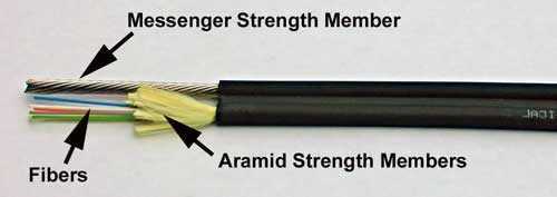
The cable known as a figure 8 cable has a cable bonded to an insulated steel or all dielectric messenger for support. The messenger is supported at each pole. If the messenger is steel, it must be grounded properly. You can also get figure 8 conduit which can be installed then cable pulled into the aerial conduit.
Aerial cables are for outside installation on poles where consideration must be given to continual tension from the cable weight as well as wind and ice loads. Regular outdoor loose tube cables can be helically lashed to a messenger or another cable (common in CATV.) Some cables have heavier jackets and stronger metal or aramid strength members to make them self supporting (called all-dielectric self-supporting or ADSS cable if the strength members are nonconductive.) Self-supporting cables use special hardware to handle the installed tension on the cables caused by the weight of the cables and environmental factors like wind. Aerial hardware to store slack cable can be mounted on the cable itself or on utility poles.
The cable known as a figure 8 cable has a cable bonded to an insulated steel or all dielectric messenger for support. The messenger is supported at each pole. If the messenger is steel, it must be grounded properly. You can also get figure 8 conduit which can be installed then cable pulled into the aerial conduit.
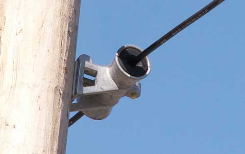
All dielectric, self-supporting cable (ADSS) uses special hardware on the poles and at the ends to distribute the tension on the cable to prevent damage.
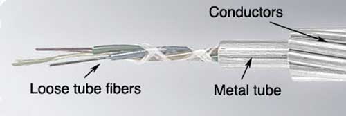
A widely used aerial cable is optical power ground wire (OPGW) which is a high voltage distribution cable with fiber in the center. The fiber is not affected by the electrical fields and the utility installing it gets fibers for grid management and communications. This cable is usually installed on the top of high voltage towers but brought to ground level for splicing or termination.
Underwater and Submarine Cables
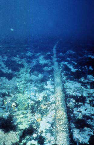
It is often necessary to install fibers under water, such as crossing a river or lake where a bridge other above water location is not possible. For simple applications a rugged direct burial cable may be adequate. For true undersea applications, cables are extremely rugged, with fibers in the middle of the cable inside stainless steel tubes and the outside coated with many layers of steel strength members and conductors for powering repeaters. Submarine cables are completed on shore, then loaded on ships and laid from the ship, often while operational to ensure proper operation.
It is often necessary to install fibers under water, such as crossing a river or lake where a bridge other above water location is not possible. For simple applications a rugged direct burial cable may be adequate. For true undersea applications, cables are extremely rugged, with fibers in the middle of the cable inside stainless steel tubes and the outside coated with many layers of steel strength members and conductors for powering repeaters. Submarine cables are completed on shore, then loaded on ships and laid from the ship, often while operational to ensure proper operation.
Even More Types Are Available: There's double-jacketed indoor/outdoor, dry water-blocked, etc. Every manufacturer has it's own specialties and sometimes their own names for common cable types, so it's a good idea to get literature from as many cable makers as possible. And check out the smaller cable companies; often they can save you a bundle by making special cable just for you, even in relative small quantities.
Air-Blown Fiber:
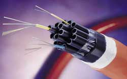
Another "cable" type is not really cable at all. By installing a
"cable" which is just a bundle of empty plastic tubes, you can "blow" fibers into the tubes
using compressed gas as needed. If you need to upgrade, blow out the
old fibers and blow in new ones. Both indoor and outdoor versions of
air-blown fiber cables are available and its even been used for FTTH. Special fibers are required that
have been coated for easier blowing through the tubes, but any
singlemode or multimode fiber is available. It's more expensive to
install since the tubes must be installed, special equipment and
trained installers are needed but can be cost effective for upgrades.
Hybrid and Composite Cables
These two types of cables are often confused, but almost everybody and the NEC defines them as:
Hybrid cables:
Cables that contain two types of fibers, usually multimode and
singlemode. These cables are often used in campus and premises
backbones where the singlemode fibers may be used in the future.
Composite cables:
Cables that contain both fibers and electrical conductors. Underwater
tethered vehicles use cables like this, as do some cables used for
remoting wireless antennas or CCTV cameras. These cables must be
properly grounded and bonded for safety.
Choosing
a cable requires consideration of all the environmental factors
involved during installation and during the cable's lifetime. Here are
some of the most important factors.
Pulling Strength: Some cable is simply laid into cable
trays or ditches, so pull strength is not too important. But
other cable may be pulled thorough 2-5 km or more of conduit. Even
with lots of cable lubricant, pulling tension can be high. Most
cables get their strength from an aramid fiber (Kevlar is the
duPont trade name), a unique polymer thread that is very strong
but does not stretch - so pulling on it will not stress the other
components in the cable. The simplest simplex cable has a pull
strength of 100-200 pounds, while outside plant cable may have
a specification of over 800 pounds.
Bending Limits:
The normal recommendation for fiber optic cable bend radius is the
minimum bend radius under tension during pulling is 20 times the
diameter of the cable. When not under tension, the minimum recommended
long term bend radius is 10 times the cable diameter.
Water Protection:
Outdoors, every cable must be protected from water or moisture.
Protection starts on the outside with a moisture resistant jacket,
usually PE (polyethylene), and a filling of water-blocking material.
The usual way has been to flood the cable with a water-blocking gel.
It's effective but messy - requiring a gel remover (use the commercial
stuff - it's best- -but bottled lemon juice works in a pinch!). A newer
alternative is dry water blocking using a water–absorbent tape or
powder – similar to the material developed to absorb moisture in
disposable diapers. Most cable manufacturers now offer dry
water-blocked cables.
Crush Loads or Rodent Penetration:
Armored cables are used because their strong jackets withstand crushing
and rodent penetration. Direct burial OSP cables are usually armored or
installed in conduit. Armored indoor cables are available with NEC
rated jackets for placement with other cables under false floors, as in
data centers.
Fire Code Ratings For Premises CablesEvery
cable installed indoors must meet fire codes. OSP cables can only be
run 50 feet (about 15 meters) inside a building without conduit or
connecting to a rated premises cable. That means the jacket must be
rated for fire resistance, with ratings for general use, riser (a
vertical cable feeds flames more than horizontal) and plenum (for
installation in air-handling areas. Most indoor cables use PVC
(polyvinyl chloride) jacketing for fire retardance. In the United
States, all premises cables must carry identification and flammability
ratings per the NEC (National Electrical Code) paragraph 770. In
Canada, it’s CEC and other countries have similar cable ratings.
These ratings
are:
| NEC Rating | Description |
| OFN | optical fiber non-conductive |
| OFC | optical fiber conductive |
| OFNG or OFCG | general purpose |
| OFNR or OFCR | riser rated cable for vertical runs |
| OFNP or OFCP | plenum rated cables for use in indoor air-handling spaces or plenums |
| OFN-LS | low smoke density |
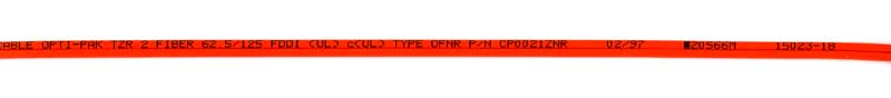
Cables without markings should
never be installed indoors as they will not pass building inspections! Outdoor
cables are not fire-rated and can only be used up to 50 feet
indoors. If you need to bring an outdoor cable indoors, consider
a double-jacketed cable with PE jacket over a PVC UL-rated indoor
jacket. Simply remove the outdoor jacket when you come indoors
and you will not have to terminate at the entry point.
Grounding and Bonding
Any cable that includes any conductive metal must be properly grounded and bonded per the NEC for safety. Indoor cables rated OFC, OFCG, OFCR or OFCP and outdoor cables with metallic strength members or armor must be grounded and bonded. All composite cables must be properly grounded and bonded also.
Cable Color Codes
Outdoor cables are generally black but premises cables are color-coded. De facto standard color codes for cable jackets have been yellow jackets for singlemode and orange jackets for multimode. With two multimode fibers now in common use, 62.5/125 and 50/125, and three versions of 50/125 fiber, a more comprehensive industry standard for color codes was required. It's important to follow the TIA-598 standard to prevent mixing up cables.
Fiber Color Codes
Inside the cable or inside each tube in a loose tube cable, individual fibers will be color coded for identification. Fibers generally follow the convention created for telephone wires except fibers are identified individually, not in pairs. Since most loose tube cables have 12 fibers per tube, colors are specified for fibers 1-12, then tubes are color coded in the same manner, up to 144 fiber cables. In ribbon cables, each ribbon is color coded in this format then ribbons are stacked. For splicing long cable runs from similar cables (called concatenation), like color fibers are spliced to ensure continuity of color codes throughout a cable run.
Inside the cable or inside each tube in a loose tube cable, individual fibers will be color coded for identification. Fibers generally follow the convention created for telephone wires except fibers are identified individually, not in pairs. Since most loose tube cables have 12 fibers per tube, colors are specified for fibers 1-12, then tubes are color coded in the same manner, up to 144 fiber cables. In ribbon cables, each ribbon is color coded in this format then ribbons are stacked. For splicing long cable runs from similar cables (called concatenation), like color fibers are spliced to ensure continuity of color codes throughout a cable run.
| Fiber Number | Color |
| 1 | Blue |
| 2 | Orange |
| 3 | Green |
| 4 | Brown |
| 5 | Slate |
| 6 | White |
| 7 | Red |
| 8 | Black |
| 9 | Yellow |
| 10 | Violet |
| 11 | Rose |
| 12 | Aqua |
Choosing
a fiber optic cable for any given application requires considering
installation and environmental requirements plus long-term fiber
requirements to cover expansion to newer communications networks.
Installation requirements include where and how the cable will be
installed, such as pulled in conduit outdoors or placed in cable trays
in a building. Long term requirements need to consider moisture or
water exposure, expected temperature range, tension (aerial cables), or
other environmental factors.
You should contact several cable manufacturers and give them detailed specifications for the installation. They will want to know where the cable is going to be installed, how many fibers you need and what kind of fibers (singlemode, multimode or both in what we call "hybrid" cables.) You can also have a "composite" cable that includes copper conductors for signals or power. The cable companies will evaluate your requirements and make suggestions. Then you can get competitive bids.
Since the plan will call for a certain number of fibers, consider adding spare fibers to the cable - fibers are cheap compared to the cost of installing additional cables. Then you won't be in trouble if you break a fiber or two when splicing, breaking-out or terminating fibers. And consider future expansion needs. Most users install many more fibers than needed, especially adding singlemode fiber to multimode fiber cables for campus or premises backbone applications.
Additional information on choosing cables is included in the chapter on fiber optic network design.
Fiber Optic Splicing and Termination
Performance Specifications/Loss
Performance Specifications/Reflectance
Splicing
Fusion Splices
Mechanical Splicing
Protecting Splices
Connectors
Termination Procedures
Prefabricated Cabling Systems
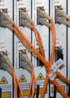
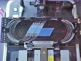
Fiber Optic Connectors (L) and Splices in Splice Tray (R)
Fiber optic joints or terminations are made two ways: 1) splices which create a permanent joint between the two fibers or 2) connectors that mate two fibers to create a temporary joint and/or connect the fiber to a piece of network gear. Either joining method must have three primary characteristics for good optical performance: low loss, minimal reflectance and high mechanical strength. Terminations must also be of the right style to be compatible to the equipment involved and be protected against the environment in which they are installed.
Splices are considered permanent joints and are used for joining most outside plant cables. Fusion splicing is most widely used as it provides for the lowest loss and least reflectance, as well as providing the most reliable joint. Virtually all singlemode splices are fusion. Mechanical splicing is used for temporary restoration and for most multimode splicing.
Connectors are used for terminations, that is the ends of the fibers where they connect to equipment or to patch panels where fiber routing can be changed by patching different fibers together. Different connectors and termination procedures are used for multimode and singlemode fibers. Multimode fibers are relatively easy to terminate, so field termination is generally done by installing connectors directly on tight buffered fibers using the procedures outlined below. Most field singlemode terminations are made by splicing a factory-made pigtail onto the installed cable rather than terminating the fiber directly as is commonly done with multimode fiber. Singlemode terminations require extreme care in assembly, especially polishing, to get good performance (low loss and reflectance), so they are usually done in a clean manufacturing facility using heat-cured epoxy and machine polishing.
Probably no fiber optic component has been given greater attention than connectors. Manufacturers have come up with over 80 styles of connectors and about a dozen different ways to install them. There are only two types of splices but numerous ways of implementing them. Fortunately for both manufacturers and installers, only a few types of either are the ones used for most applications.
Performance Specifications
Connector and Splice Loss
The primary specification for connectors or splices is loss or the amount of light lost in the connection.
When we say connector
loss, we really mean "connection" loss - the loss of a mated pair of
connectors, expressed in "dB." Thus, testing connectors requires mating them to reference
connectors which must be high quality connectors themselves to not
adversely affect the measured loss when mated to an unknown connector. This
is an important point often not fully explained. In
order to measure the loss of the connectors you must mate them to a
similar, known good, connector. When a connector being tested is mated
to several different connectors, it may have different losses, because
those losses are dependent on the reference connector it is mated to.
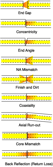 Connection and splice loss
is caused by a number of factors. Loss is minimized when the
two fiber cores are identical and perfectly aligned (more on the effects of fiber geometry and alignment), the connectors
or splices are properly finished and no dirt is present. Only
the light that is coupled into the receiving fiber's core will
propagate, so all the rest of the light becomes the connector
or splice loss.
Connection and splice loss
is caused by a number of factors. Loss is minimized when the
two fiber cores are identical and perfectly aligned (more on the effects of fiber geometry and alignment), the connectors
or splices are properly finished and no dirt is present. Only
the light that is coupled into the receiving fiber's core will
propagate, so all the rest of the light becomes the connector
or splice loss.
End gaps cause two problems,
insertion loss and reflectance. The emerging cone of light from
the connector will spill over the core of the receiving fiber
and be lost. In addition, the air gap in the joint between the fibers causes
a reflection when the light encounters the change n refractive
index from the glass fiber to the air in the gap. This reflection
(called fresnel reflection) amounts to about 5% in typical flat
polished connectors, and means that no connector with an air
gap will have less than about 0.3 dB loss. This reflection is called
to as reflectance or optical return loss, which can be a
problem in laser based systems. Connectors use a number of polishing
techniques to create convex fiber ends that ensure physical contact of the fiber ends to minimize
reflectance. On mechanical splices, it is possible to reduce
back reflection by using non-perpendicular cleaves, which cause
back reflections to be absorbed in the cladding of the fiber.
The end of the fiber must
be properly polished and clean to minimize loss. A rough surface will scatter
light and dirt can scatter and absorb light. Since the optical
fiber is so small, typical airborne dirt can be a major source
of loss. Whenever connectors are not terminated, they should
be covered with dust caps provided by the manufacturer to protect the end of the ferrule from dirt. One should
never touch the end of the ferrule, since the oils on one's skin
causes the fiber to attract dirt. Before connection and testing,
it is advisable to clean connectors with lint-free wipes moistened
with isopropyl alcohol or special dry fiber cleaners.
Two sources of loss caused by mismatched fibers are directional;
numerical aperture (NA) and core diameter differences inherent in the fibers being joined. Differences in these
two will create connections that have different losses depending
on the direction of light propagation. Light from a fiber with
a larger NA will overfill the core of the receiving fiber be more sensitive to angularity and end gap,
so transmission from a fiber of larger NA to one of smaller NA
will be higher loss than the reverse direction. Likewise, light from a
larger core fiber will have high loss coupled to a fiber of smaller
diameter, while one can couple a small diameter fiber to a large
diameter fiber with minimal loss, since it is much less sensitive
to end gap or lateral offset.
These
fiber mismatches occur for two reasons, the occasional need to
interconnect two dissimilar fibers and production variances in fibers
of the same nominal dimensions. Production variances are only a few
microns and contribute only small amounts of loss, but the loss caused
by mismatches will be directional, causing larger losses when
transmitting from larger to smaller core fibers.
With two multimode fibers in common usage today (50/125 and 62.5/125) and two
others which have been used occasionally in the past (100/140 and 85/125) and several
types of singlemode fiber in use, it is possible to sometimes
have to connect dissimilar fibers or use systems designed for
one fiber size on another. If you connect a smaller
fiber to a larger one, the coupling losses will be minimal, often
only the fresnel loss (about 0.3 dB). But connecting larger fibers
to smaller ones results in substantial losses, not only due to
the smaller cores size, but also the smaller NA of most small
core fibers.
Typical connector losses are generally less than 0.3 dB for factory-polished singlemode or multimode
connectors using adhesive/polish techniques. Few installers tackle
singlemode field termination, generally fusion splicing factory-made
pigtails onto the fibers, since SM polishing is not so easy in the
field, especially in terms of reflectance. Multimode field terminations
are common, since experienced installers can get results comparable to
factory-terminations with adhesive/polish techniques. Field termination
of prepolished/splice connectors using a precision cleaver (those made
for fusion splicing) can produce consistent results around 0.5 dB,
while the simple cleaver produces losses more often in the 0.75 dB
range. Few industry standards put numbers on connector losses, but TIA
568 calls for connection losses of less than 0.75 dB, a high number but
one which will allow use of prepolished/splice connectors.
Reflectance
or optical return loss (which has also been called "back reflection")
of the connector is the amount of light that is
reflected back up the fiber toward the source by light reflections off
the interface of the polished end surface of the connector and air. It
is called fresnel reflection and is caused by the light going through
the change in index of refraction at the interface between the fiber
(n=1.5) and air (n=1). Reflectance is primarily a problem with
connectors but may also affect mechanical splices which contain an
index matching gel to prevent reflectance.
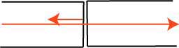
Reflectance
one component of the connector's loss, representing
about 0.3 dB loss for a non-contact or air-gap connector where the two
fibers do not make contact. Minimizing the reflectance is necessary to
get maximum performance out of high bit rate laser systems and
especially AM modulated CATV systems. In multimode systems, reflections
are
less of a problem but can add to background noise in the fiber.
Since
this is more a problem with singlemode systems, manufacturers have
concentrated on solving the problem for their singlemode components but
multimode connectors benefit also since any reduction in reflectance also reduces loss. Several schemes have been used to
reduce reflectance, mainly using a convex physical contact (PC) polish
on the end of the connector ferrule, which reduces the fresnel
reflection. The technique involves polishing the end surface of the
fiber to a convex surface or even better at a slight angle (APC or
angled physical contact) to prevent reflectance.
See Connector Ferrule Shapes
& Polishes below for more information on connector ferrule endface polish to reduce reflectance.
See Measuring Reflectance to see the methods and issues of measuring reflectance.
See Measuring Reflectance to see the methods and issues of measuring reflectance.
Splices create a permanent joint between two fibers, so its use is limited to places where cables are not expected to be available for servicing in the future. The most common application for splicing is concatenating (joining) cables in long outside plant cable runs where the length of the run requires more than one cable. Splicing can be used to mix a number of different types of cables such as connecting a 48 fiber cable to six 8 fiber cables going to various locations. Splicing is generally used to terminate singlemode fibers by splicing preterminated pigtails onto each fiber. And of course, splicing is used for OSP restoration.
Splicing
is more common in outside plant (OSP) applications than premises
cabling, where most cables are pulled in one piece and directly terminated. Splicing is only
needed if the cable runs are too long for one straight pull or you need
to mix a number of different types of cables (like bringing a 48 fiber
cable in and splicing it to six 8 fiber cables.) And of course, we
often use splices for OSP restoration, after the number one problem of
outside plant cables, a dig-up and cut of a buried cable, usually
referred to as "backhoe fade" for obvious reasons!
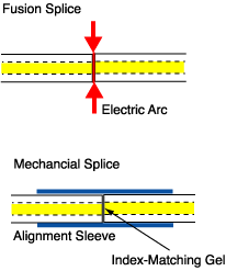
There are two types of
splices, fusion and mechanical. Fusion splicing is most widely used as
it provides for the lowest loss and least reflectance, as well as
providing the strongest and most reliable joint. Fusion splicing
machines are available in two types that splice a single fiber or a
ribbon of 12 fibers at one time. Virtually all singlemode splices are
fusion. Mechanical splicing is mostly used for temporary restoration
and for multimode splicing. In the photo below, a fusion splice is on
the left and the rest are various types of mechanical splices.
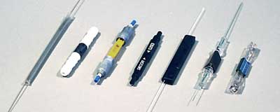
Splices: fusion on the far left, other types of mechanical splices.
Splices: fusion on the far left, other types of mechanical splices.
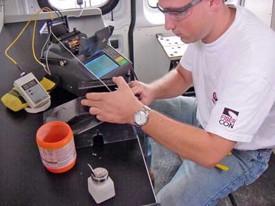
Fusion SplicesFusion plices are made by "welding" the two fibers together usually by an electric arc. To be safe, you should not do that in an enclosed space like a manhole or an explosive atmosphere, and the equipment is too bulky for most aerial applications, so fusion splicing is usually done above ground in a truck or trailer set up for the purpose. (photo above) Splicing on poles is obviously dangerous too. It’s easier to bring extra cable length into a trailer on the ground and work in a clean environment for splicing, placing splices in a closure and testing. The final closure is then placed in location and the extra fiber carefully looped and mounted in an appropriate place.
Today's singlemode fusion splicers are automated and you have a hard time making a bad splice as long as you cleave the fiber properly. The biggest application is singlemode fibers in outside plant installations. Fusion splices are so good today that splice points may not be detectable in OTDR traces. Some splicing machines can do one fiber at a time but Mass Fusion Splicers can do all 12 fibers in a ribbon at once. Fusion splicers cost $15,000 to $40,000, but the splices only cost a few dollars each.
The Fusion Splicing Process
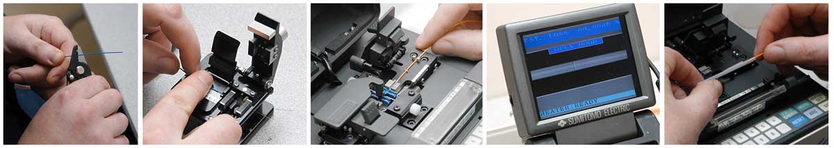
Preparing the Fibers
The fusion splicing process is basically the same for all automatic splicing machines. The first step is to strip, clean & cleave the fibers to be spliced. Strip the primary buffer coating to expose the proper length of bare fiber. Clean the fiber with appropriate wipes. Cleave the fiber using the directions appropriate to the cleaver being used. Place each fiber into the guides in the fusion splicing machine and clamp it in place.
Running the splicer program
First choose the proper program for the fiber types being spliced. The splicer will show the fibers being spliced on a video screen. Fiber ends will be inspected for proper cleaves and bad ones will be rejected. That fiber must be cleaved again. The fibers will be moved into position, prefused to remove any dirt on the fiber ends and preheat the fibers for splicing. The fibers will be aligned using the core alignment method used on that splicer. Then the fibers will be fused by an automatic arc cycle that heats them in an electric arc and feeds the fibers together at a controlled rate.
When fusion is completed, the splicing machine will inspect the splice and estimate the optical loss of the splice. It will tell the operator if a splice needs to be remade. The operator removes the fibers from the guides and attach a permanent splice protector by heat-shrinking or clamping clam shell protectors.
Mass (Ribbon) Fusion Splicing
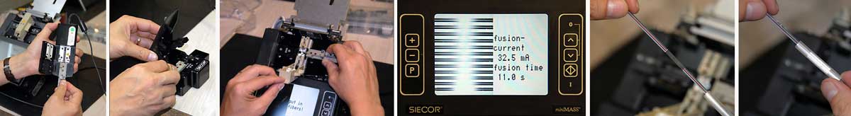
Ribbon cables are fusion spliced one ribbon at a time, rather than one fiber at a time. Thus each ribbon is stripped, cleaved and spliced as a unit. Special tools are needed to strip the fiber ribbon, usually heating it first, then cleave all fibers at once. Many tools place the ribbon in a carrier that supports and aligns it through stripping, cleaving and splicing. Consult both cable and splicer manufacturers to ensure you have the proper directions.
Mechanical Splicing
Mechanical splices are alignment fixtures that hold the ends of two fibers together with some index matching gel or glue between them. There are a number of types of mechanical splices, like little glass tubes or V-shaped metal clamps. The tools to make mechanical splices are cheap, but the splices themselves are more expensive. Many mechanical splices are used for restoration, but they can work well with both singlemode and multimode fiber, with practice - and using a quality cleaver such as those used for fusion splicing.
Mechanical Splicing Process
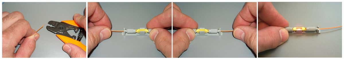
Preparing the Fibers
The splicing process is basically the same for all types of mechanical splices. The first step is to strip, clean & cleave the fibers to be spliced. Strip the primary buffer coating to expose the proper length of bare fiber. Clean the fiber with appropriate wipes. Cleave the fiber using the directions appropriate to the cleaver being used. Using a high quality cleaver such as those provided with fusion splicers will yield more consistent and lower loss splices.
Making The Mechanical Splice
Insert the first fiber into the mechanical splice. Most splices are designed to limit the depth of the fiber insertion by the stripped length of buffer coating on the fiber. Clamp the fiber in place if fibers are held separately. Some splices clamp both fibers at once. Repeat these steps for the second fiber.
You can optimize the loss of a mechanical splice visually using a visual fault locator, a visible laser test source if the fiber ends being spliced are visible. Gently withdraw one of the fibers a slight amount, rotating it slightly and reinserting it until the visible light is minimized, indicating lowest loss.
Individual fibers and buffer tubes in loose tube cables are color coded for identification. When splicing similar cables on long runs, fibers should be spliced straight through according to color codes to continue the same color coding for each joined fiber in the concatenated cables. When connecting large fiber count cables to several smaller cables, fibers should be spliced in order and records kept of the connections made.
Protecting Splices
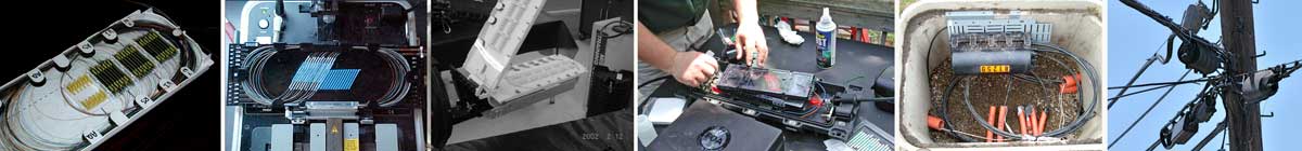
For protection against the outside plant environment and damage, splices require placement in a protective case. They are generally placed in a splice tray which is then placed inside a splice closure for OSP installations or a patch panel box for premises applications. Indoors, splice trays are often integrated into patch panels to provide for connections to the fibers.
There are probably thousands of different types and options on splice closures. Some are designed for concatenation of long distance cables where two identical cables are spliced together. Some closures are designed for connecting several smaller cables to a larger one for breaking out the larger cable to several destinations. Closures can be used for midspan entry also, where the cable jacket is stripped but most of the buffer tubes are coiled inside without opening, while one or more tubes will be opened and spliced to other cables. Some have cables entering into one end, some have cable entries on both ends.
There are splice closures designed to be buried, mounted on walls, hung from cables or poles. Some are small pedestals themselves. Each type has a particular application and probably every application has a special closure. Even special hardware may be necessary for handling different cable or splice types, so make certain you have the right hardware before using the closure. It is recommended that you work with vendors to find the best closure for your applications then follow their instructions.
Preparing cables for splice closures involves several steps that should be followed in the exact sequence specified by the manufacturer to ensure the cables are properly secured and the closure will seal. For every splice closure, it is important to follow the manufacturer’s instructions on stripping the cable to ensure proper lengths of strength members to secure the cable to the closure and proper lengths of buffer tubes to connect to the splice trays. The proper length of fiber is needed to allow splicing and then neatly storing fiber in the splice tray. Inside splice closures and at each end, cables with metallic shielding or strength members must be properly grounded and bonded.
Care should be taken when arranging fibers and splices in splice trays and buffer tubes in the splice closure to prevent stress on the fibers. Arranging fibers inside splice trays may require twisting the fiber but following the closure manufacturer’s instructions will minimize the stress on the fiber. Often the fibers are broken as the trays and closure are assembled or re-entered for troubleshooting and repair. Cables must be secured to the splice closure and sealed properly. Generally loose tube cables will have the tubes extending from the entrance of the closure to the tray, where they are secured, then approximately 1 meter of bare fibers are organized in the tray after splicing. Care must be taken to properly bond electrical conductors such as the armor on some cables or center metallic strength members to the closure and at each end.
All closures must be sealed to prevent moisture entry. Closures must be properly secured, with the location being determined by the installation type, and excess cable properly coiled and stored. This may be in a pedestal or vault, on a pole or tower or buried underground.
Which Splice ?
If cost is the issue, fusion requires expensive equipment and but makes cheap splices, while mechanical splices require inexpensive equipment and expensive splice hardware. So if you make a lot of splices (like thousands in an big telco or CATV network) use fusion splices. If you need just a few, use mechanical splices.
Fusion splices give very low back reflections and are preferred for singlemode high speed digital or CATV networks. However, they may not work well some multimode fibers, so mechanical splices may be preferred for MM, unless it is an underwater or aerial application, where the greater reliability of the fusion splice is preferred.
Making Good Splices
Making consistently low loss splices depends on proper techniques and keeping equipment in good shape. Cleanliness is a big issue, of course. Fiber strippers should be kept clean and in good condition and be replaced when nicked or worn. Cleavers are most important, as the secret to good splices - either fusion or mechanical - is having good cleaves on both fibers. Keep cleavers clean and have the scribing blades aligned and replaced regularly. Fusion splicers should be properly maintained and fusing parameters set for the fibers being spliced. For mechanical splices, light pressure on the fiber to keep the ends together while crimping is important. Use a visual fault locator (VFL) to optimize the splice before crimping if possible.
Making consistently low loss splices depends on proper techniques and keeping equipment in good shape. Cleanliness is a big issue, of course. Fiber strippers should be kept clean and in good condition and be replaced when nicked or worn. Cleavers are most important, as the secret to good splices - either fusion or mechanical - is having good cleaves on both fibers. Keep cleavers clean and have the scribing blades aligned and replaced regularly. Fusion splicers should be properly maintained and fusing parameters set for the fibers being spliced. For mechanical splices, light pressure on the fiber to keep the ends together while crimping is important. Use a visual fault locator (VFL) to optimize the splice before crimping if possible.
Verifying Splice Loss
Splices are permanent joints that cannot be accessed for individual insertion loss testing with a source and power meter as connectors are tested. Fusion splicers generally provide an estimate of connector loss based on an analysis of data from the alignment system used by the splicer, but it is only an estimate. An insertion loss test of the entire finished cable will be done when installation is finished, but that only allows comparison to the overall loss predicted by the loss budget created during the design phase, not verification of any individual splice.
For concatenations of cables, only an OTDR can see the splice and confirm its loss, but for accurate loss measurements it requires testing from both ends and averaging (see Chapter 8 on Testing.) The OTDR test will also confirm that the splice is not reflective, an important issue in many systems. The limited resolution of the OTDR means that it cannot be used to verify the splices used to terminate fibers with pigtails, but a visual fault locator can be used to check these splices near the ends of the cable.
Connectors
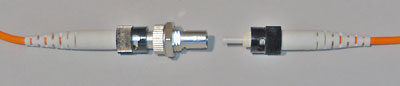
Most fiber optic connectors are plugs or so-called male connectors with a protruding ferrule that holds the fibers and aligns two fibers for mating. They use a mating adapter to mate the two connectors that fits the securing mechanism of the connectors (bayonet, screw-on or snap-in.) The ferrule design is also useful as it can be used to connect directly to active devices like LEDs, VCSELs and detectors.
Different connectors and termination procedures are used for singlemode and multimode connectors. Multimode fibers are relatively easy to terminate, so field termination is generally done by installing connectors directly on tight buffered fibers using the procedures outlined below. Most field singlemode terminations are made by splicing a factory-made pigtail onto the installed cable rather than terminating the fiber directly as is commonly done with multimode fiber. Singlemode terminations require extreme care in assembly, especially polishing, to get good performance (low loss and reflectance), so they are usually done in a clean manufacturing facility using heat-cured epoxy and machine polishing.
Choosing a connector type for any installation should consider if the connector is compatible with the systems planned to utilize the fiber optic cable plant, if the termination process is familiar to the installer and if the connector is acceptable to the customer. If the systems are not yet specified, hybrid patchcords with different connectors on each end may be necessary. If the installer is not familiar with connector installation, training may be necessary. And sometimes, the user may have been sold on a connector type that is not ideal for the installation, so the installer should discuss the merits of other types before committing to the project.
Splices are permanent joints that cannot be accessed for individual insertion loss testing with a source and power meter as connectors are tested. Fusion splicers generally provide an estimate of connector loss based on an analysis of data from the alignment system used by the splicer, but it is only an estimate. An insertion loss test of the entire finished cable will be done when installation is finished, but that only allows comparison to the overall loss predicted by the loss budget created during the design phase, not verification of any individual splice.
For concatenations of cables, only an OTDR can see the splice and confirm its loss, but for accurate loss measurements it requires testing from both ends and averaging (see Chapter 8 on Testing.) The OTDR test will also confirm that the splice is not reflective, an important issue in many systems. The limited resolution of the OTDR means that it cannot be used to verify the splices used to terminate fibers with pigtails, but a visual fault locator can be used to check these splices near the ends of the cable.
Connectors
Most fiber optic connectors are plugs or so-called male connectors with a protruding ferrule that holds the fibers and aligns two fibers for mating. They use a mating adapter to mate the two connectors that fits the securing mechanism of the connectors (bayonet, screw-on or snap-in.) The ferrule design is also useful as it can be used to connect directly to active devices like LEDs, VCSELs and detectors.
Different connectors and termination procedures are used for singlemode and multimode connectors. Multimode fibers are relatively easy to terminate, so field termination is generally done by installing connectors directly on tight buffered fibers using the procedures outlined below. Most field singlemode terminations are made by splicing a factory-made pigtail onto the installed cable rather than terminating the fiber directly as is commonly done with multimode fiber. Singlemode terminations require extreme care in assembly, especially polishing, to get good performance (low loss and reflectance), so they are usually done in a clean manufacturing facility using heat-cured epoxy and machine polishing.
Choosing a connector type for any installation should consider if the connector is compatible with the systems planned to utilize the fiber optic cable plant, if the termination process is familiar to the installer and if the connector is acceptable to the customer. If the systems are not yet specified, hybrid patchcords with different connectors on each end may be necessary. If the installer is not familiar with connector installation, training may be necessary. And sometimes, the user may have been sold on a connector type that is not ideal for the installation, so the installer should discuss the merits of other types before committing to the project.
Styles of Fiber Optic Connectors
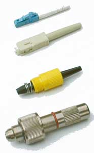 Since
fiber optic technology was introduced in the late 70s, numerous
connector styles have been developed - probably over 100 designs. Each new design was meant to
offer better performance (less light loss and reflectance) and easier,
faster and/or more inexpensive termination.
Since
fiber optic technology was introduced in the late 70s, numerous
connector styles have been developed - probably over 100 designs. Each new design was meant to
offer better performance (less light loss and reflectance) and easier,
faster and/or more inexpensive termination.
Of
course, the marketplace eventually
determines which connectors are successful. However several attempts to
standardize connectors have been attempted. Some were unique to systems or networks. FDDI, the first fiber LAN,
and ESCON, the IBM mainframe
peripheral network, required unique connectors. TIA 568
originally called for SC connectors as a standard, but when users continued
to use more STs than SCs and a whole new generation of smaller
connectors were introduced, TIA-568B was changed to say that any
connector standardized by a FOCIS standard document was acceptable.
The
four connectors shown at left show how fiber optic connectors have
evolved. The bottom connector is a Deutsch 1000, the first
commercially-available fiber optic connector. It was really a
mechanical splice, where fibers were held inside the connector with a
tiny screw-tightened chuck. The nose piece was spring-loaded, allowing
exposing the fiber for cleaving and mating with a small plastic lens in
a mating adapter. The mating adapter also had index-matching fluid to
reduce loss but it was a dirt problem.
The
yellow connector is an AT&T Biconic. It was developed by Jack Cook
at Bell Labs in the late 1970s. The conical ferrule was molded from
glass-filled plastic. The first Biconics had ferrules molded around the
fiber, until a die with a tiny 125 micron pin in the exact center was
developed. When Biconics were adapted to singlemode fiber, the ferrules
were ground on a special grinding machine to center the fiber.
The
SC, which was introduced in the mid-1980s, used a new invention, the
molded ceramic ferrule, that revolutionized fiber optic termination.
Ceramic was an ideal ferrule material. It could be made cheaply by
molding, much cheaper than machining metal for example. It was
extremely
stable with temperature, having similar expansion characteristics to
glass which prevented "pistoning" when the ferrule came unglued, a
problem with metal or plastic ferrules. It's hardness was similar
to glass which made polishing much easier. And it readily
adhered to fibers using epoxies or anaerobic adhesives.
Today, virtually all connectors use the ceramic ferrule, usually 2.5 mm
diameter (SC, ST, FC) or 1.25 mm (LC, MU.)
The
LC connector was introduced in the late 1990s to miniaturize connectors
for higher density in patch panels or equipment. It uses a smaller
ceramic ferrule, 1.25 mm diameter. The LC is the connector of choice
for telecom and high speed data (>1 Gb/s) networks.
Guide to Identifying Fiber Optic Connectors
Check out the "spotters
guide" below and you will see the most common fiber optic
connectors. (All the photos are to the same scale except the MTP, so you can
get an idea of the relative size of these connectors.)
| ST (an AT&T Trademark) is the one of the most popular connectors for multimode networks, like most buildings and campuses. It has a bayonet mount and a long cylindrical ferrule to hold the fiber. Most ferrules are ceramic, but some are metal or plastic. And because they are spring-loaded, you have to make sure they are seated properly. If you have high loss, reconnect them to see if it makes a difference. | 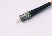 |
| FC/PC has been one of the most popular singlemode connectors for many years. It screws on firmly, but make sure you have the key aligned in the slot properly before tightening. It's being replaced by SCs and LCs. | 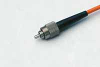 |
| SC is a snap-in connector that is widely used in singlemode systems for it's excellent performance and multimode systems because it was the first connector chosen as the standard connector for TIA-568 (now any connector with a FOCIS standard is acceptable.) It's a snap-in connector that latches with a simple push-pull motion. It is also available in a duplex configuration. | 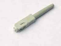 |
| The
ST/SC/FC/FDDI/ESON connectors have the same ferrule size - 2.5 mm or
about 0.1 inch - so they can be mixed and matched to each other using
hybrid mating adapters. This makes it convenient to test, since you can
have a set of multimode reference test cables with ST or SC connectors
and adapt to all these connectors. From the top: ST>FC SC>FC SC>ST | 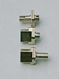 |
| LC is a new connector that uses a 1.25 mm ferrule, half the size of the ST. Otherwise, it's a standard ceramic ferrule connector, easily terminated with any adhesive. Good performance, highly favored for singlemode and the connector of choice for multimode transceivers for gigabit speeds and above, including multimode Ethernet and Fibre Channel. | 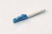 |
| MT-RJ is a duplex connector with both fibers in a single polymer ferrule. It uses pins for alignment and has male and female versions. Multimode only, field terminated only by prepolished/splice method. | 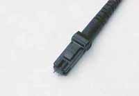 |
| Opti-Jack is a neat, rugged duplex connector cleverly designed around two ST-type ferrules in a package the size of a RJ-45. It has male and female (plug and jack) versions. | 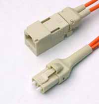 |
| Volition is a simple, inexpensive duplex connector that uses no ferrule at all. It aligns fibers in a V-groove like a splice. Plug and jack versions, but one can field terminate jacks only. | 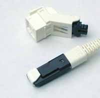 |
| MU looks a miniature SC with a 1.25 mm ferrule. It's more popular in Japan. | 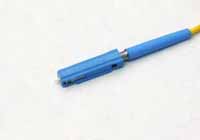 |
|
MTP is a 12 fiber connector for
ribbon cable. It's main use is for preterminated cable assemblies. | 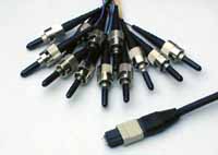 |
The ST/SC/FC/FDDI/ESCON connectors
have the same ferrule size - 2.5 mm or about 0.1 inch diameter- so they
can be mixed and matched to each other using hybrid mating adapters.
This makes it convenient to test, since you can have a set of
multimode reference test cables with ST connectors and adapt
to all these connectors. Likewise, the LC and MU use the same ferrule (1.25 mm diameter) so mating is possible.
- Connector Popularity
The ST is still one of the most popular multimode connectors because it is inexpensive and easy to install. The SC connector was specified as a standard by the old EIA/TIA 568A specification, but its higher cost and difficulty of installation (until recently) limited its popularity in premises applications at first. However, newer SCs are much better in both cost and installation ease, so it has been growing in use, but is now challenged by the LC, which is the connector of choice for transceivers for systems operating at gigabit speeds because of its small size and high performance.
Singlemode networks have used FC or SC connectors in about the same proportion as ST and SC in multimode installations. There are some D4s out there too. But LCs have become the most popular, again for their performance and small size.- EIA/TIA 568 now allows any fiber optic connector as long as it has a FOCIS (Fiber Optic Connector Intermateability Standard) document behind it. This opened the way to the development of several new connectors, which we call the "Small Form Factor" (SFF) connectors, including AT&T LC, the MT-RJ, the Panduit "Opti-Jack," 3M's Volition, the E2000/LX-5 and MU. The LC has been particularly successful in the US.
Specialty Fiber Optic Connectors

There are a number of specialty fiber optic connectors available such as this multifiber military connector, special underwater or aircraft connectors, plastic optical fiber (POF) connectors, etc. Most have been designed for very specific applications and require extremely rigorous qualification testing. Some like the Mil-C-38999, are copper wiring connectors adapted to hold fiber optic ferrules. Many of these connectors require special cable types, termination procedures, cleaning, handling and test procedures. Refer to manufacturer's instructions whenever dealing with these types of connectors.
- Connector Ferrule Shapes & Polishes
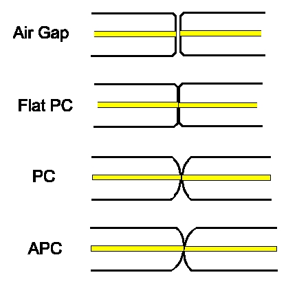
- Fiber optic connectors can have several different ferrule shapes or finishes, usually referred to as end finish or polish types. Early connectors, which did not have keyed ferrules and could rotate in mating adapters, always had an air gap between the connectors to prevent them rotating and grinding scratches into the ends of the fibers. The ends of the ferrules were polished on hard,flat surfaces.
- Beginning with the ST and FC which had keyed ferrules, the connectors were designed to contact tightly, what we now call physical contact (PC) connectors. These connectors were still polished flat on the end. Reducing the air gap reduced the loss and reflectance (very important to laser-based singlemode systems ), since light has a loss of about 5% (~0.25 dB) at each air gap and light is reflected back up the fiber. While air gap connectors usually had losses of 0.5 dB or more and a reflectance of -20 dB, PC connectors had typical losses of 0.3 dB and a reflectance of -30 to -40 dB. PC connectors required polishing on a flat surface with a soft rubber pad to allow the end to be polished convex.
- Soon thereafter, it was determined that polishing the connector ferrules to a convex end face would produce an even better connection. The convex ferrule guaranteed the fiber cores were in contact. Losses were under 0.3dB and reflectance -40 dB or better.
- The ultimate solution for singlemode systems extremely sensitive to reflections, like CATV or high bitrate telco links, was to angle the end of the ferrule 8 degrees to create what we call an APC or angled PC connector. Then any reflected light is at an angle that is absorbed in the cladding of the fiber, resulting in reflectance of >-60 dB.
Connector Color Codes:
Since the earliest days of fiber optics, orange, black or gray was multimode and yellow singlemode. However, the advent of metallic connectors like the FC and ST made color coding difficult, so colored boots were often used.
The TIA 568 color code for connector bodies and/or boots is Beige for multimode fiber except aqua for laser-optimized fiber, Blue for singlemode fiber, and Green for APC (angled) connectors.
- Termination Procedures
Whatever you do, always follow the manufacturer's termination instructions closely. - Multimode connectors are usually installed in the field on the cables after pulling, while singlemode connectors are usually installed by splicing a factory-made "pigtail" onto the fiber. The tolerances on singlemode terminations are much tighter than multimode and the polishing processes are more critical, so singlemode termination is better done in a factory environment using polishing machines (left, below). You can install singlemode connectors in the field for low speed data networks, but you may not be able to get losses lower than 1 dB and reflectance may be a problem! Multimode connectors are easier to install and polish (below, right) so are often done in the field by trained technicians.
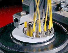
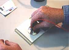
- Connectors can be installed directly on most cable types, including jacketed tight buffer types like simplex, zipcord and breakout cables, where the where the aramid fiber strength members in the cable are crimped or glued to the connector body to create a strong connector. Connectors can be attached to the 900 micron buffered fibers in distribution cables, but the termination is not as rugged as those made to jacketed cables, so they should be placed in patch panels or boxes for protection. The 250 micron buffered fibers in loose tube cables cannot be easily terminated unless they have a reinforcement called a breakout kit or furcation kit installed, where each fiber is covered by a larger plastic tube. Generally loose tube and ribbon cables are terminated by splicing on a terminated pigtail.
- Cables can be pulled with connectors already on them if, and a big if, you can deal with two issues: First, the length must be precise. Too short and you have to pull another longer one (its not cost effective to splice), too long and you waste money and have to store the extra cable length. Secondly, the connectors must be protected. Some cable and connector manufacturers offer protective sleeves to cover the connectors, but you must still be much more careful in pulling cables. You might consider terminating one end and pulling the unterminated end to not risk the connectors. There is a growing movement to install preterminated systems with the MTP 12 multifiber connector. It's tiny not much bigger than a ST or SC, but has up to 12 fibers. Manufacturers sell multifiber cables with MTPs on them that connect to preterminated patch panels with STs or SCs. (See "Do You Have To Terminate In The Field" below.)
Multimode Terminations: Several
different types of terminations are available for multimode fibers.
Each version has its advantages and disadvantages, so learning
more about how each works helps decide which one to use.
Singlemode Terminations:
Singlemode fiber requires different connectors and polishing techniques
that are best done in a factory environment. Consequently most SM fiber
is field terminated by splicing on a factory-terminated pigtail. Singlemode
termination requires special connectors with much tighter tolerances on
the ferrule, especially the hole for the fiber. Polishing requires
special diamond polishing film on a soft rubber pad and a polishing
slurry to get low reflectance. But you can put SM connectors on
in the field if you know what you are doing. Expect higher loss
and high reflectance.
Termination Processes
Adhesive/Polish Terminations:
Most connectors use epoxies or other adhesives to hold the fiber in the
connector ferrule and polish the end of the fiber to a smooth finish. Follow
termination procedures carefully, as they have been developed to
produce the lowest loss and most reliable terminations. Use only the
specified adhesives, as the fiber to ferrule bond is critical for low
loss
and long term reliability! We've seen people use hardware store
epoxies, Crazy Glue, you name it! And they regretted doing it. Only
adhesives approved by manufacturers or other distributors of connectors
should be used. If the adhesive fails, not unusual when connector ferrules
were made of metal, the fiber will "piston" - sticking out or pulling
back into the ferrule - causing high loss and potential damage to a
mated connector.
The polishing process involves three steps which only takes a minute: "air polishing" to grind down the protruding fiber, polishing on a soft pad with the fiber held perpendicular to the polishing surface with a polishing puck and a quick final fine polish.
The polishing process involves three steps which only takes a minute: "air polishing" to grind down the protruding fiber, polishing on a soft pad with the fiber held perpendicular to the polishing surface with a polishing puck and a quick final fine polish.
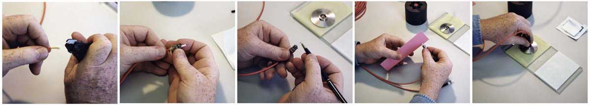
Epoxy/Polish:
Most connectors, including virtually all factory made terminations, are
the simple "epoxy/polish" type where the fiber is glued into the
connector with epoxy and the end polished with special polishing film.
These provide the most reliable connection, lowest losses (less than
0.5 dB) and lowest costs, especially if you are doing a lot of
connectors. The small bead of hardened epoxy that surrounds the fiber
on the end of the ferrule even makes the cleaving and polishing
processes much easier - practically foolproof. The epoxy can be allowed
to set overnight or cured in an inexpensive oven. A "heat gun" should
never be used to try to cure the epoxy faster as the uneven heat may
not cure all the epoxy or may overheat some of it which will prevent it
ever curing. Don't use "Hot Melt" ovens either, as they use a much
higher temperature and will ruin the epoxy.
"Hot Melt" Adhesive/Polish: This
is a 3M trade name for a connector that already has the epoxy (actually
a heat set glue) inside the connector. You insert the connector in a special oven. In a few
minutes, the glue is melted, so you remove the connector, insert the stripped fiber, let it cool
and it is ready to polish. Fast and easy, low loss, but not as cheap as
the epoxy type, it has become the favorite of lots of contractors who
install relatively small quantities of connectors. Remember you need a
special Hot Melt oven, as it needs a much higher temperature than is
used for curing epoxy.
Anaerobic Adhesive/Polish:
These connectors use a quick setting "anaerobic" adhesive to replace
the epoxy or Hot Melt adhesive that cures faster than other types of
adhesives. They work well if your technique is good, but some do not
have the wide temperature range of epoxies. A lot of installers are
using Loctite 648, with or without the accelerator solution, that is
neat and easy to use.
Crimp/Polish: Rather than glue
the fiber in the connector, these connectors use a crimp on the
fiber to hold it in. Early types offered "iffy" performance,
but today they are pretty good, if you practice a lot. Expect
to trade higher losses for the faster termination speed. And
they are more costly than epoxy polish types. A good choice if
you only install small quantities and your customer will accept
them.
Prepolished/Splice Connectors (also called "cleave & crimp")
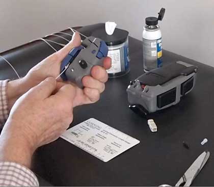
Some manufacturers offer connectors that have a short stub fiber already epoxied into the ferrule and polished and a mechanical splice in the back of the connector, so you just cleave a fiber and insert it like a splice, a process which can be done very quickly. Several connectors use a fusion splice instead of a mechanical splice to attach the connector, a better process but requiring more expensive equipment - a fusion splicer, sometimes a dedicated splicer for that connector.
This method has both good and bad points. The manufacturing process is complex so these connectors are costly, as much as ten times as much as an adhesive/polish type, since they require careful manufacturing. Some of that extra cost can be recovered in lower labor costs for installation. You must have a good cleave on the fiber you are terminating to make them low loss, as the fiber cleave is a major factor in the loss of a mechanical splice. Using a high quality cleaver like those used for fusion splicing, available from some manufacturers as part of their termination kits, is recommended. Even if you do everything correctly, loss will be somewhat higher, because you have a connection loss plus a splice loss in every connector. The best way to terminate them is to verify the loss of the splice with a visual fault locator and "tweak" them. (Photo: Corning, Unicam)
termination types under Components.
Hints for doing field terminations
Here are a few things to remember when you are terminating connectors in the field. Following these guidelines will save you time, money and frustration.
Here are a few things to remember when you are terminating connectors in the field. Following these guidelines will save you time, money and frustration.
Choose the connector carefully and clear it with the customer
if it is anything other than an epoxy/polish type. Some customers
have strong opinions on the types or brands of connectors used
in their job. Find out first, not later!
Never, never, NEVER take a new
connector in the field until you have installed enough of them
in the office that you can put them on in your sleep. The field
is no place to experiment or learn! It'll cost you big time!
Have the right tools for the
job. Make sure you have the proper tools and they are in good
shape before you head out for the job. This includes all the
termination tools, cable tools and test equipment. Do you know
your test cables are good? Without that, you will test good terminations
as bad every time. More and more installers are owning their
own tools like auto mechanics, saying that is the only way to
make sure the tools are properly cared for.
Dust and dirt are your enemies. It's very hard to terminate or
splice in a dusty place. Try to work in the cleanest possible
location. Use lint-free wipes (not cotton swaps or rags made
from old T-shirts!) to clean every connector before connecting
or testing it. Don't work under heating vents, as they are blowing
dirt down on you continuously.
Don't overpolish. Contrary to common sense, too much polishing is just
as bad as too little. The ceramic ferrule in most of today's connector
is much harder than the glass fiber. Polish too much will cause
undercutting of the fiber and you create a concave fiber surface not
convex as it should be, increasing the loss. A few swipes is all it
takes.
Change polishing film regularly. Polishing builds up residue
and dirt on the film that can cause problems after too many connectors
and cause poor end finish. Check the manufacturers' specs.
Put covers on connectors and patch panels when not in use. Keep
them covered to keep them clean.
Inspect and test, then document. It is very hard to troubleshoot
cables when you don't know how long they are, where they go or
how they tested originally! So keep good records, smart users
require it and expect to pay extra for good records.
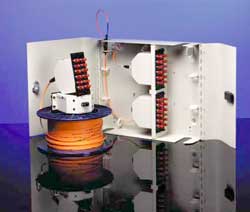
Not
necessarily. Many manufacturers offer prefabricated fiber optic
cabling systems for both premises and outside plant systems. In fact,
the largest application for prefabricated
systems is fiber to the home
(FTTH) where it saves a tremendous amount of time in installation and
cost. Using prefab systems requires knowing precisely where the cable
will be run so cable lengths can be specified. Using CAD systems and
design drawings, a complete
fiber optic cabling system is designed to the customer's specifications
and built in a factory using standard components. Early prefabricated
systems (some are still available) simply terminated cables with
standard connectors like STs or SCs and put them inside a plastic
pulling boot with a pulling loop attached to the fiber strength
members. The cable would be placed with the boot in place then removed
to connect into patch panels.
Today, it's
more common to use backbone cables terminated in small multifiber MTP
connectors that are pulled from room to room and connected to
rack-mounted modules that have MTP connectors on the back and single
fiber connectors on the front (see photo of Fiberware system.) Like
everything else, there are tradeoffs. The factory-assembled connectors
usually have lower loss than field terminations but the MTP connectors,
even factory assembled, are not low loss, so the total loss may be more
than field terminated systems. Costs also involve tradeoffs, as factory
systems are more expensive for the components but installation time is
much less.
In new facilities, considering prefabricated systems is always a good idea, but all factors
should be considered before making a decision.
Jump To:
Connector Inspection by Microscope Optical Power Optical Loss OTDR Testing
CD, PMD, SA Testing
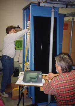
After fiber optic cables are installed, spliced
and terminated, they must be tested. For every fiber optic
cable plant, you need to test for continuity and polarity, end-to-end
insertion loss and then troubleshoot any problems. If it's a long outside
plant cable with intermediate splices, you will probably want
to verify the individual splices with an OTDR test also, since that's
the only way to make sure that each splice is good. If you are the
network user, you may also be interested in testing transmitter and receiver power, as
power is the measurement that tells you whether the system is
operating properly.
Testing
is the subject of the majority of industry standards, as there is a
need to verify component and system specifications in a consistent
manner. A list of TIA fiber optic standards
is on the FOA website in Tech Topics. Perhaps the most important test
is insertion loss of an installed fiber optic cable plant performed
with a light source and power meter (LSPM) or optical loss test set (OLTS)
which is required by all international standards to ensure the cable
plant is within the loss budget before acceptance of the installation.
Testing
fiber optic components and cable plants requires making several tests
and measurements with the most common tests listed below. Some tests
involve installer inspection and judgment, such as visual inspection or
tracing while some use sophisticated instruments that provide direct
measurements. Optical power, required for measuring source power,
receiver power and, when used with a test source, loss or attenuation,
is the most important parameter and is required for almost every fiber
optic test. Backscatter measurements made by an OTDR are the next most
important measurements, especially for testing outside plant
installations and troubleshooting. Measurement of geometrical
parameters of fiber and bandwidth or dispersion are essential for fiber
manufacturers but not relevant to field testing. Troubleshooting
installed cables and networks is required in every installation.
Testing fiber optics requires special tools
and instruments which must be chosen to be appropriate for the components or cable plants being tested.
Visual Inspection
Visual Inspection
Visual Tracing
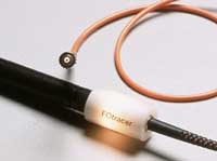 Continuity checking with a visual fiber tracer makes certain the fibers are not broken and
to trace a path of a fiber from one end to another through many
connections, verifying duplex connector polarity for example. It looks like a flashlight
or a pen-like instrument with a light bulb or LED source that mates
to a fiber optic connector. Attach the fiber to test to the visual
tracer and look at the other end of the fiber to see the light transmitted
through the core of the fiber. If there is no light at the end,
go back to intermediate connections to find the bad section of
the cable.
Continuity checking with a visual fiber tracer makes certain the fibers are not broken and
to trace a path of a fiber from one end to another through many
connections, verifying duplex connector polarity for example. It looks like a flashlight
or a pen-like instrument with a light bulb or LED source that mates
to a fiber optic connector. Attach the fiber to test to the visual
tracer and look at the other end of the fiber to see the light transmitted
through the core of the fiber. If there is no light at the end,
go back to intermediate connections to find the bad section of
the cable.
A good example of how it can
save time and money is testing fiber on a reel before you pull
it to make sure it hasn't been damaged during shipment. Look
for visible signs of damage (like cracked or broken reels, kinks
in the cable, etc.) . For testing, visual tracers help also identify
the next fiber to be tested for loss with the test kit. When
connecting cables at patch panels, use the visual tracer to make
sure each connection is the right two fibers! And to make certain
the proper fibers are connected to the transmitter and receiver,
use the visual tracer in place of the transmitter and your eye
instead of the receiver (remember that fiber optic links work
in the infrared so you can't see anything anyway.)
Visual Fault Location
 A higher power version of the fiber tracer called a visual fault locator (VFL)
uses a visible laser that
can also find faults. The red laser light is powerful enough for
continuity checking or to trace
fibers for several kilometers, identify splices in splice trays and show breaks in
fibers or high loss connectors. You can actually see the loss of light
at a fiber break by the
bright red light from the VFL through the jacket of many
yellow or orange
simplex cables (excepting black or gray jackets, of course.) It's
most important use is finding faults in short cables or near the
connector where OTDRs cannot find them.
A higher power version of the fiber tracer called a visual fault locator (VFL)
uses a visible laser that
can also find faults. The red laser light is powerful enough for
continuity checking or to trace
fibers for several kilometers, identify splices in splice trays and show breaks in
fibers or high loss connectors. You can actually see the loss of light
at a fiber break by the
bright red light from the VFL through the jacket of many
yellow or orange
simplex cables (excepting black or gray jackets, of course.) It's
most important use is finding faults in short cables or near the
connector where OTDRs cannot find them.
You
can also use this gadget to visually verify and optimize mechanical
splices or prepolished-splice type fiber optic connectors. By visually
minimizing the light lost you can get the lowest loss splice. In fact-
don't even think of doing one of those prepolished-splice
type connectors without one. No other method will
assure you of high yield with those connectors.
A note on VFL eye safety.
VFLs use visible light. You will find it uncomfortable to look at the
output of a fiber illuminated by a VFL. That's good, because the power
level is high and you should not be looking at it. When tracing fibers,
look from the side of the fiber to see if light is present.
Fiber optic inspection microscopes are used to inspect connectors
to confirm proper polishing and find faults like scratches, polishing defects and dirt. They can be
used both to check the quality of the termination procedure and
diagnose problems. A well made connector will have a smooth , polished,
scratch free finish and the fiber will not show any signs of cracks,
chips or areas where the fiber is either protruding from the end of the
ferrule or pulling back into it.
The
magnification for viewing connectors can be 30 to 400 power but it is
best to use a medium magnification. If the magnification is too low,
critical details may not be visible. Inspecting with a very high
magnification may cause the viewer to be too critical, rejecting good
connectors. Multimode connectors should use magnifications in the range
of 100-200X and singlemode fiber can use higher magnification, up to
400X. A better solution is to use medium magnification, but
inspect the connector three ways: viewing directly at the end of the
polished surface with coaxial or oblique lighting, viewing directly
with light transmitted through the core, and viewing at an angle with
lighting from the opposite angle or with quite oblique lighting.
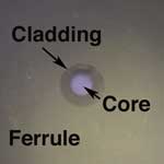
Viewing directly allows seeing the fiber and the ferrule hole, determining if the ferrule hole is of the proper size, the fiber is centered in the hole and a proper amount of adhesive has been applied. Only the largest scratches may be visible this way, however. Adding light transmitted through the core will make cracks in the end of the fiber, caused by pressure or heat during the polish process, visible.
Viewing the end of the connector at an angle, while lighting it from the opposite side at approximately the same angle or using low-angle lighting and viewing directly will allow the best inspection for the quality of polish and possible scratches. The shadowing effect of angular viewing or lighting enhances the contrast of scratches against the mirror smooth polished surface of the glass.
One needs to be careful in inspecting connectors, however. The tendency is to sometimes be overly critical, especially at high magnification. Only defects over the fiber core are generally considered a problem. Chipping of the glass around the outside of the cladding is not unusual and will have no effect on the ability of the connector to couple light in the core on multimode fibers. Likewise, scratches only on the cladding should not cause any loss problems.
The best microscopes allow you to inspect the connector from several angles, either by tilting the connector or having angle illumination to get the best picture of what's going on. Check to make sure the microscope has an easy-to-use adapter to attach the connectors of interest to the microscope.
Video readout microscopes are now available that allow easier viewing of the end face of the connector and some even have software that analyzes the finish. While they are much more expensive than normal optical microscopes, they will make inspection easier and greatly increase productivity.
Remember to check that no power is present in the cable before you look at it in a microscope to protect your eyes! The microscope will concentrate any power in the fiber and focus it into your eye with potentially hazardous results. Some microscopes have filters to stop the infrared radiation from transmitters to minimize this problem.
Practically
every measurement in fiber optics refers to optical power. The output
of a transmitter or the input to receiver are "absolute" optical power
measurements, that is, you measure the actual value of the power. Loss
is a "relative" power measurement, the difference between the power
coupled into a component like a cable, splice or a connector and the
power that is transmitted through it. This difference in power level
before and after the component is what we call optical loss and defines
the performance of a cable, connector, splice, or other component.
Whenever tests are performed on fiber optic networks, the results are displayed on an instrument readout. Power measurements are expressed in "dB," the measurement unit of power and loss in optical fiber measurements. Optical loss is measured in “dB” while optical power is measured in “dBm.” Loss is a negative number (like -3.2 dB) as are many power measurements. Measurements in dB can sometimes be confusing.
In the early days of fiber optics, source output power was usually measured in milliwatts, a linear scale, and loss was measured in dB or decibels, a logarithmic scale. Over the years, all measurements migrated to dB for convenience causing much confusion. Loss measurements were generally measured in dB since dB is a ratio of two power levels, one of which is considered the reference value. The dB is a logarithmic scale where each 10 dB represents a ratio of 10 times. The actual equation used to calculate dB is
dB = 10 log (measured power / reference power).
Thus 10 dB is a ratio of 10 times (either 10 times as much or one-tenth as much), 20 dB is a ratio of 100, 30 dB is a ratio of 1000, etc. When the two optical powers compared are equal, dB = 0, a convenient value that is easily remembered. If the measured power is higher than the reference power, dB will be a positive number, but if it is lower than the reference power, it will be negative. Thus measurements of loss are typically expressed as a negative number.
Measurements of optical power such as the output of a transmitter or input to a receiver are expressed in units of dBm. The “m” in dBm refers to a reference power of 1 milliwatt. Thus a source with a power level of 0 dBm has a power of 1 milliwatt. Likewise, -10 dBm is 0.1 milliwatt and +10 dBm is 10 milliwatts.
To measure loss in a fiber optic system, we make two measurements of power, a reference measurement before the component we are testing and a loss measurement after the light passes through the component. Since we are measuring loss, the measured power will be less than the reference power, so the ratio of measured power to reference power is less than 1 and the log is negative, making dB a negative number. When we set the reference value, the meter reads “0 dB” because the reference value we set and the value the meter is measuring is the same. Then when we measure loss, the power measured is less, so the meter will read “- 3.0 dB” for example, if the tested power is half the reference value. Although meters measure a negative number for loss, convention is the loss is expressed as a positive number, so we say the loss is 3.0 dB when the meter reads - 3.0 dB.
Instruments that measure in dB can be either optical power meters or optical loss test sets (OLTS). The optical power meter usually reads in dBm for power measurements or dB with respect to a user-set reference value for loss. While most power meters have ranges of +3 to -50 dBm, most sources are in the range of +10 to -10 dBm for lasers and -10 to -20 dBm for LEDs. Only lasers used in CATV or long-haul telephone systems have powers high enough to be really dangerous, up to +20 dBm; that’s 100 milliwatts or a tenth of a watt.
It is important to remember that dB is for measuring loss, dBm is for measuring power and the more negative a number is, the higher the loss. Set your zero reference before measuring loss and check it occasionally while making measurements.
Calibration of Power Measurements
Calibrating fiber optic power measurement equipment requires setting up a reference standard traceable to a national standards lab like the National Institute of Standards and Technology in the US for comparison purposes while calibrating every power meter or other instrument. The NIST standard for all power measurements is an ECPR, or electrically calibrated pyroelectric radiometer, which measures optical power by comparing the heating power of the light to the well-known heating power of a resistor. Calibration is done at 850, 1300 and 1550 nm. Sometimes, the wavelength of lasers at 1310 nm is used by manufacturers as the calibrated wavelength on a power meter, but the standard for power meter calibration is 1300 nm. To conveniently transfer their laboratory standard to fiber optic power meter manufacturers calibration laboratories, NIST currently uses a laboratory optical power meter which is sent around to labs as a transfer standard.
Meters calibrated in this manner have an uncertainty of calibration of about +/- 5%, compared to the NIST primary standards. Limitations in the uncertainty are the inherent inconsistencies in optical coupling, about 1% at every transfer, and slight variations in wavelength calibration. NIST is working continuously with instrument manufacturers and private calibration labs to try to reduce the uncertainty of these calibrations.
Recalibration of instruments should be done annually, however experience has shown that the accuracy of meters rarely changes significantly during that period, as long as the electronics of the meter do not fail. The calibration of fiber optic power meters requires considerable investment in capital equipment so meters must be returned to the original manufacturer or private calibration labs for calibration.
Understanding FO Power Meter Measurement Uncertainty
Much attention has been paid to developing transfer standards for fiber optic power measurements. The US NIST in Boulder, Colorado and standards organizations of most other countries have worked to provide good standards to work from. We can now assure traceability for our calibrations, but even so the errors involved in making measurements are not ignorable. Even when fiber optic power meters are calibrated within specifications, the uncertainty of a measurement may be as great as +/- 5% (about 0.2 dB) compared to standards. Understanding power meter errors and their probable causes will insure a realistic viewpoint on fiber optic power measurements.
The first source of error is optical coupling. Light from the fiber is expanding in a cone. It is important that the detector to fiber geometry be such that all the light from the fiber hits the detector, otherwise the measurement will be lower than the actual value. But every time light passes through a glass to air interface, such as the window on the detector, a small amount of the light is reflected and lost. Finally, the cleanliness of the optical surfaces involved can cause absorption and scattering. The sum total of these potential errors will be dependent on the connector type, wavelength, fiber size and NA.
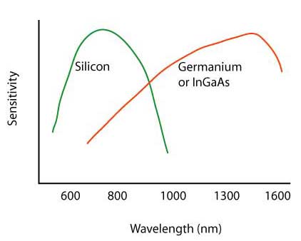
Beyond the coupling errors, one has errors associated with the wavelength calibration. Semiconductor detectors used in fiber optic instruments (and systems too) have a sensitivity that is wavelength dependent. Since the actual source wavelength is rarely known, there is an error associated with the spectral sensitivity of the detector. By industry convention, the three cardinal wavelengths (850, 1300 and 1550 nm) are used for all power measurements, not the exact source wavelength.
Another source of error exists for high and low level measurements. At high levels, the optical power may overload and saturate the detector, causing the measurement to be in error. At low levels, the inherent detector noise adds to the signal and becomes an error. If the signal is 10 dB above the noise floor (10 time the noise), the offset error is 10% or 0.4 dB.
Instrument Resolution vs. Measurement Uncertainty
Considering the uncertainty of most fiber optic measurements, instrument manufacturers have provided power and loss meters with a measurement resolution that is usually much greater than needed. The uncertainty of optical power measurements is about 0.2 dB (5%), loss measurements are more likely to have uncertainties of 0.2-0.5 dB or more, and optical return loss measurements have a 1 dB uncertainty.
Instruments which have readouts with a resolution of 0.01 dB are generally only appropriate for laboratory measurements of very low component losses or changes caused by environmental changes. Within the laboratory, a resolution of 0.01 dB can be extremely useful, since one often measures the loss of connectors or splices that are under 0.10 dB or changes in loss under environmental stress that are under 0.1 dB. Stability of sources and physical stress on cables limits measurement uncertainty to about 0.02 to 0.05 dB per day, but 0.01 dB resolution can be helpful in determining small changes in component performance.
Field measurements have higher uncertainty because more components are measured at once and losses are higher. Practically, measurements are better when the instrument resolution is limited to 0.1dB. Readings will be more likely to be stable when being read and more indicative of the measurement uncertainty.
Take a minute and read about "dB," the measurement unit of power and loss in optical fiber measurements.
Much attention has been paid to developing transfer standards for fiber optic power measurements. The US NIST in Boulder, Colorado and standards organizations of most other countries have worked to provide good standards to work from. We can now assure traceability for our calibrations, but even so the errors involved in making measurements are not ignorable. Even when fiber optic power meters are calibrated within specifications, the uncertainty of a measurement may be as great as +/- 5% (about 0.2 dB) compared to standards. Understanding power meter errors and their probable causes will insure a realistic viewpoint on fiber optic power measurements.
The first source of error is optical coupling. Light from the fiber is expanding in a cone. It is important that the detector to fiber geometry be such that all the light from the fiber hits the detector, otherwise the measurement will be lower than the actual value. But every time light passes through a glass to air interface, such as the window on the detector, a small amount of the light is reflected and lost. Finally, the cleanliness of the optical surfaces involved can cause absorption and scattering. The sum total of these potential errors will be dependent on the connector type, wavelength, fiber size and NA.
Beyond the coupling errors, one has errors associated with the wavelength calibration. Semiconductor detectors used in fiber optic instruments (and systems too) have a sensitivity that is wavelength dependent. Since the actual source wavelength is rarely known, there is an error associated with the spectral sensitivity of the detector. By industry convention, the three cardinal wavelengths (850, 1300 and 1550 nm) are used for all power measurements, not the exact source wavelength.
Another source of error exists for high and low level measurements. At high levels, the optical power may overload and saturate the detector, causing the measurement to be in error. At low levels, the inherent detector noise adds to the signal and becomes an error. If the signal is 10 dB above the noise floor (10 time the noise), the offset error is 10% or 0.4 dB.
Instrument Resolution vs. Measurement Uncertainty
Considering the uncertainty of most fiber optic measurements, instrument manufacturers have provided power and loss meters with a measurement resolution that is usually much greater than needed. The uncertainty of optical power measurements is about 0.2 dB (5%), loss measurements are more likely to have uncertainties of 0.2-0.5 dB or more, and optical return loss measurements have a 1 dB uncertainty.
Instruments which have readouts with a resolution of 0.01 dB are generally only appropriate for laboratory measurements of very low component losses or changes caused by environmental changes. Within the laboratory, a resolution of 0.01 dB can be extremely useful, since one often measures the loss of connectors or splices that are under 0.10 dB or changes in loss under environmental stress that are under 0.1 dB. Stability of sources and physical stress on cables limits measurement uncertainty to about 0.02 to 0.05 dB per day, but 0.01 dB resolution can be helpful in determining small changes in component performance.
Field measurements have higher uncertainty because more components are measured at once and losses are higher. Practically, measurements are better when the instrument resolution is limited to 0.1dB. Readings will be more likely to be stable when being read and more indicative of the measurement uncertainty.
Take a minute and read about "dB," the measurement unit of power and loss in optical fiber measurements.
Measuring Power With A Fiber Optic Power Meter
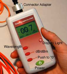
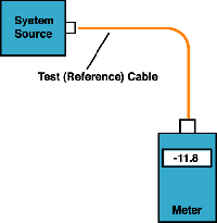
Measuring
power requires only a power meter (most come with a screw-on adapter
that matches the connector being tested), a known good fiber optic
cable (of the right fiber size, as coupled power is a function of the
size of the core of the fiber) and a little help from the network
electronics to turn on the transmitter. Remember when you measure
power, the meter must be set to the proper range (usually dBm,
sometimes microwatts, but never "dB" - that's a relative power range
used only for testing loss! Read about "dB") and the proper
wavelength , matching the source being used in the system (850, 1300, 1550 nm for glass fiber, 650 or 850 nm for POF). Refer to the
instructions that come with the test equipment for setup and
measurement instructions (and don't wait until you get to the
job site to try the equipment, try it in the office first!)
To measure power, attach the meter to the cable attached to the source that has the output you want to measure (see diagram to the right). That can be at the receiver to measure receiver power, or using a reference test cable (tested and known to be good) that is attached to the transmitter to measure output power. Turn on the transmitter/source and give it a few minutes to stabilize. Set the power meter for the matching wavelength and note the power the meter measures. Compare it to the specified power for the system and make sure it's enough power but not too much.
To measure power, attach the meter to the cable attached to the source that has the output you want to measure (see diagram to the right). That can be at the receiver to measure receiver power, or using a reference test cable (tested and known to be good) that is attached to the transmitter to measure output power. Turn on the transmitter/source and give it a few minutes to stabilize. Set the power meter for the matching wavelength and note the power the meter measures. Compare it to the specified power for the system and make sure it's enough power but not too much.
More on measuring Power.
- Optical loss is the primary performance parameter of most fiber optic components. For fiber, it’s the loss per unit length or attenuation coefficient. For connectors, it’s connection loss when mated to another connector. For cables, it’s the total loss of the components of the cable, including connectors, fiber, splices and any other components in the cable run being tested. We’ll use cables to illustrate insertion loss then look at other components.
- Loss of a cable is the difference between the power coupled into the cable at the transmitter end and what comes out at the receiver end. Testing for loss (also called "insertion loss") requires measuring the optical power lost in a cable (including fiber attenuation, connector loss and splice loss) with a fiber optic light source and power meter (LSPM) or optical loss test set (OLTS.) Loss testing is done at wavelengths appropriate for the fiber and its usage. Generally multimode fiber is tested at 850 nm and optionally at 1300 nm with LED sources. Singlemode fiber is tested at 1310 nm and optionally at 1550 nm with laser sources.
- Most loss testing is done on cable assemblies, either patchcords or installed cable plants. But fiber manufacturers test every fiber for loss to calculate its attenuation coefficient. Connector manufactures test many connectors to obtain an average value of the loss the connector will have when terminated on fibers. Other component manufacturers also test the loss of their components to verify their performance.
An insertion loss measurement is made by mating the cable being tested to
known good reference cables with a calibrated launch power that becomes
the "0 dB" loss reference. Why
do you need reference cables to measure loss? Why can't you just plug the cable to test
into a source and power meter and measure the power? There are several
reasons:
1)You need a cable to measure the output power of the source for calibration of "0 dB" loss.
2) In order to measure the loss of the connectors you must mate them to a similar, known good, connector.
This is an important point often not fully explained. When we say connector loss, we really mean "connection" loss - the loss of a mated pair of connectors. Thus, testing connectors requires mating them to reference connector which must be high quality connectors themselves to not adversely affect the measured loss when mated to an unknown connector.
3)Testing with reference cables on each end simulates a cable plant with patchcords connecting to transmission equipment.
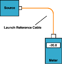
Fiber Optic Test SourcesIn
addition to a power meter, you need a test source. The test source
should match the type fiber ( generally LED for MM or laser for SM) and wavelength (850,
1300, 1550 nm) that will be used on the fiber optic cable you are
testing. If you are testing to some standards, you may need to add some
mode conditioning, like a mandrel wrap, to meet the standard launch
conditions.
A fiber optic test source must be chosen for compatibility with the type of fiber in use (singlemode or multimode with the proper core diameter) and the wavelength desired for performing the test. Most sources are either LED's or lasers of the types commonly used as transmitters in actual fiber optic systems, making them representative of actual applications and enhancing the usefulness of the testing. Some laboratory tests, such as measuring the attenuation of fiber over a range of wavelengths requires a variable wavelength source, which is usually a tungsten lamp with a monochromator to vary the light source wavelength.
Typical wavelengths of sources are 650 or 665 nm (plastic fiber), 820, 850 and 870 nm (short wavelength multimode fiber ) and 1300 (long wavelength multimode fiber) or 1310 nm and 1550 nm (long wavelength singlemode fiber). LED's are typically used for testing multimode fiber and lasers are used for singlemode fiber, although there is some crossover. High speed LANs which use multimode fiber may be tested with VCSELs like the system sources and short singlemode jumper cables may be tested with LEDs.
The source wavelength can be a critical issue in making accurate loss measurements on long links, since the attenuation coefficient of the fiber is wavelength sensitive. Thus all test sources should be calibrated for wavelength in case corrections for wavelength variations are required.
Test sources almost always have fixed connectors. Hybrid test jumpers with connectors compatible with the source on one end and the connector being tested on the other must be used as reference cables. This may affect the type of reference setting mode used for loss testing.
Source-related factors affecting measurement accuracy are the stability of the output power and the modal distribution launched into multimode fiber. Source stability is mainly a factor of the electronic circuitry in the source. Industry standards have requirements on the modal output of test sources for multimode fiber that are important to the manufacturers of the test sources. Various standards have called for mode scramblers, filters and strippers to adjust the modal distribution in the fiber to approximate actual operating conditions. Today, most standards call for sources to meet output requirements and for a mode conditioner to be used in testing. The effects of mode power distribution on multimode measurements are covered in the chapter on optical fiber.
Reference Cables
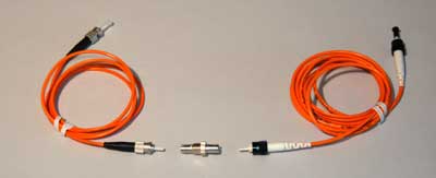
Reference cables and mating adapter
Loss testing requires one or two reference cables, depending on the test performed and the appropriate mating adapters for the connectors. Reference cables are typically 1-2 meters long, with fiber and connectors matching the cables to be tested. The accuracy of the measurement will depend on the quality of the reference cables, since they will be mated to the cable under test. The quality and cleanliness of the connectors on the launch and receive cables is one of the most important factors in the accuracy of loss measurements. Always test reference cables by the patchcord or single ended method shown below to make sure they are in good condition before you start testing other cables.
Standards
groups have not been able to successfully specify the quality of
reference cables in terms of tightly toleranced components like the
fiber and connectors but only by the insertion loss of the connectors
on the cables when tested with other high quality test cables. The best
recommendation for qualifying reference
cables is to choose cables with low loss, tested "single-ended" per
FOTP-171 below.
In
order to mate the reference cables to the cables you want to test, you
need mating adapters. Mating adapters are as important to low
connection loss as the quality of the connectors since the mating
adapter is responsible for aligning the two connector ferrules
correctly. Mating adapters must be kept clean, like connectors and
discarded after some number of uses as they wear out from repeated
matings. Mating adapters may have alignment sleeves made from plastic,
metal or ceramic. Plastic alignment sleeves used on the cheapest mating
adapters should not be used for testing as they wear out in only a few
insertions, leaving dusty residue on the connectors. Metal adapters are
good for many more insertions and provide a better alignment, so they
are acceptable. Ceramic alignment sleeves are the best, providing the
best alignment and practically never wearing out.
Testing Loss
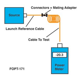
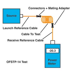
There
are two methods that are used to measure loss, a "patchcord test" which
we call "single-ended loss" (TIA FOTP-171) and an "installed cable
plant test" we call "double-ended loss" (TIA OFSTP-14 (MM) and
OFSTP-7 (SM).) Single-ended loss uses only the launch cable, while
double-ended loss uses a receive cable attached to the meter also when making the loss measurement.
Single-ended loss is measured
by mating the cable you want to test to the reference launch
cable and measuring the power out the far end with the meter.
When you do this you measure the loss of the connector mated
to the launch cable and the loss of any fiber, splices or
other connectors in the cable you are testing.
Since you are aiming the connector on the far end of the cable mated to
the power meter at a large area detector instead of mating it to
another connector, it effectively has no loss so it is not included in
the measurement. This method is described in FOTP-171 and is
shown in the drawing. An advantage to this test is you can troubleshoot
cables to find a bad connector since you can reverse the cable to test
the connectors on the each end individually.
In a double-ended loss test,
you attach the cable to test between two reference cables, one
attached to the source and one to the meter. This way,
you measure two connectors' loses, one on each end, plus the
loss of all the cable or cables, including connectors and splices, in between. This is the method
specified in OFSTP-14 (multimode, the singlemode test is OFSTP-7), the standard test for loss in an installed cable
plant.
- Setting a "0 dB" Loss Reference
- In order to measure loss, it is first necessary to set a reference launch power for loss which becomes the 0 dB value. Correct setting of the 0 dB reference power is critical to making good loss measurements.
- For single-ended testing, the reference power for 0 dB is set at the end of the reference cable. Simply attach the power meter to the end of the cable, measure the output power and, with most meters, set that as the reference for loss measurements. The meter will then read the loss of each cable tested directly.
More Than One Way to Set "0" dB Loss Reference
- There are three methods of setting the reference for a double-ended test, using one, two or three reference cables, and the method chosen will affect the measured loss. Why are there three methods? The three methods developed because of the variations in connector styles and how test equipment is made.
One Cable Reference
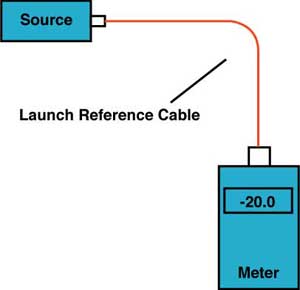
Most fiber optic connectors are constructed so that the fiber is held in a protruding ferrule, called a “plug” style connector. Two plug connectors are mated using a mating adapter that holds the ferrules in alignment and allows them to meet in the center. If connectors like these are being tested and the test equipment has interfaces that fit those connectors, the single cable reference (OFSTP-14 Method B) can be used. This method is the simplest method and generally considered the method of choice as no connections are included when setting the 0 dB reference.
After setting a reference, the launch cable is detached from the meter, but not the source. The launch reference cable should never be removed from the source after setting the reference to ensure the launch power remains constant. The receive cable is attached to the meter and then both reference cables are attached to the cable to test. The loss reading will include both connections to the cable under test and the loss of the fiber and any other components in the cable itself.
Two Cable Reference
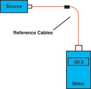
If the test equipment has an interface for a different style of connector, so the connectors on the cables being tested cannot be attached to the instruments, a two cable reference method (OFSTP-14 Method A) can be used. Reference cables must be hybrid cables with connectors on one end to match the interfaces of the instruments and the other end to mate to the connectors on the cable to be tested. The 0 dB reference is set by attaching both reference cables to the instruments and connecting the other ends with a mating adapter. After setting the reference, the two cables are disconnected at the middle and the cable to be tested inserted in between them.
The loss reading will include both connections to the cable under test and the loss of the fiber and any other components in the cable itself less the loss of the connection between the two reference cables when setting the reference. Thus loss measured using the two cable reference will be lower than the one cable reference by the connection included when setting the reference. The uncertainty of this connection loss included in the reference also adds to the uncertainty of the loss measurement of any cables tested in this manner.
Three Cable Reference
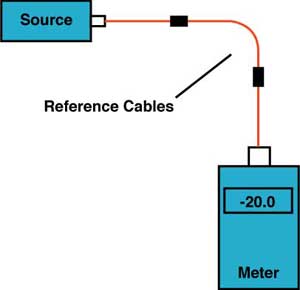
Some fiber optic connectors are “plug” and “jack” style connectors where one has a protruding ferrule while the other has a jack or receptacle. Some have alignment pins that are only on one side, like the MTP connector where pins are used on the jack side. They are generally used with plugs on both ends of patchcords and jacks or receptacles on the permanently installed cables terminated in racks or outlets.
Either of these two styles of connectors can only be mated to an appropriate style of connector, making it hard to do a one or two cable reference. The solution is a three cable reference (OFSTP-14 Method C), where the hybrid cables attached to the instruments for reference cables are terminated in plugs and a third cable terminated in jacks is inserted between them to create a 3 cable reference. After setting the reference, the two reference cables are disconnected from the third cable at the middle and the cable to be tested inserted in between them in place of the reference cable.
As before, the loss reading will include both connections to the cable under test and the loss of the fiber and any other components in the cable itself less the loss of the two connections between the third reference cable and the two reference cables when setting the reference. Since the third cable is usually only a short length of fiber with connections on each end, the loss of the fiber is ignorable. The loss measured using the three cable reference will be lower than the one cable reference by the two connections included when setting the reference. The uncertainty of these two connection losses included in the reference also adds to the uncertainty of the loss measurement of any cables tested in this manner.
While this three cable method has the highest uncertainty, it is the only method that works for any connectors and any test equipment. Therefore, it has become the preferred method in several international standards.
The most popular method and the method called for in TIA-568 is the one cable method, "Method B," it's designation in OFSTP-14.
Choosing a Reference Method
Some reference books and manuals show setting the reference power for loss using only a launch reference cable, both a launch and receive cable mated with a mating adapter or even three reference cables. Industry standards, in fact, include all three methods of setting a "0dB loss" reference. The two or three cable reference methods are acceptable for some tests and are the only way you can test some connectors, but it will reduce the loss you measure by the amount of loss between your reference cables when you set your "0dB loss" reference. Also, if any of the reference cables are bad, setting the reference with the cables does not reveal that problem. Then you could begin testing with bad launch cables making all your loss measurements wrong. This means that it is very important to inspect and test reference cables to ensure they are in good condition.
Most fiber optic connectors are constructed so that the fiber is held in a protruding ferrule, called a “plug” style connector. Two plug connectors are mated using a mating adapter that holds the ferrules in alignment and allows them to meet in the center. If connectors like these are being tested and the test equipment has interfaces that fit those connectors, the single cable reference (OFSTP-14 Method B) can be used. This method is the simplest method and generally considered the method of choice as no connections are included when setting the 0 dB reference.
After setting a reference, the launch cable is detached from the meter, but not the source. The launch reference cable should never be removed from the source after setting the reference to ensure the launch power remains constant. The receive cable is attached to the meter and then both reference cables are attached to the cable to test. The loss reading will include both connections to the cable under test and the loss of the fiber and any other components in the cable itself.
Two Cable Reference
If the test equipment has an interface for a different style of connector, so the connectors on the cables being tested cannot be attached to the instruments, a two cable reference method (OFSTP-14 Method A) can be used. Reference cables must be hybrid cables with connectors on one end to match the interfaces of the instruments and the other end to mate to the connectors on the cable to be tested. The 0 dB reference is set by attaching both reference cables to the instruments and connecting the other ends with a mating adapter. After setting the reference, the two cables are disconnected at the middle and the cable to be tested inserted in between them.
The loss reading will include both connections to the cable under test and the loss of the fiber and any other components in the cable itself less the loss of the connection between the two reference cables when setting the reference. Thus loss measured using the two cable reference will be lower than the one cable reference by the connection included when setting the reference. The uncertainty of this connection loss included in the reference also adds to the uncertainty of the loss measurement of any cables tested in this manner.
Three Cable Reference
Some fiber optic connectors are “plug” and “jack” style connectors where one has a protruding ferrule while the other has a jack or receptacle. Some have alignment pins that are only on one side, like the MTP connector where pins are used on the jack side. They are generally used with plugs on both ends of patchcords and jacks or receptacles on the permanently installed cables terminated in racks or outlets.
Either of these two styles of connectors can only be mated to an appropriate style of connector, making it hard to do a one or two cable reference. The solution is a three cable reference (OFSTP-14 Method C), where the hybrid cables attached to the instruments for reference cables are terminated in plugs and a third cable terminated in jacks is inserted between them to create a 3 cable reference. After setting the reference, the two reference cables are disconnected from the third cable at the middle and the cable to be tested inserted in between them in place of the reference cable.
As before, the loss reading will include both connections to the cable under test and the loss of the fiber and any other components in the cable itself less the loss of the two connections between the third reference cable and the two reference cables when setting the reference. Since the third cable is usually only a short length of fiber with connections on each end, the loss of the fiber is ignorable. The loss measured using the three cable reference will be lower than the one cable reference by the two connections included when setting the reference. The uncertainty of these two connection losses included in the reference also adds to the uncertainty of the loss measurement of any cables tested in this manner.
While this three cable method has the highest uncertainty, it is the only method that works for any connectors and any test equipment. Therefore, it has become the preferred method in several international standards.
The most popular method and the method called for in TIA-568 is the one cable method, "Method B," it's designation in OFSTP-14.
Choosing a Reference Method
Some reference books and manuals show setting the reference power for loss using only a launch reference cable, both a launch and receive cable mated with a mating adapter or even three reference cables. Industry standards, in fact, include all three methods of setting a "0dB loss" reference. The two or three cable reference methods are acceptable for some tests and are the only way you can test some connectors, but it will reduce the loss you measure by the amount of loss between your reference cables when you set your "0dB loss" reference. Also, if any of the reference cables are bad, setting the reference with the cables does not reveal that problem. Then you could begin testing with bad launch cables making all your loss measurements wrong. This means that it is very important to inspect and test reference cables to ensure they are in good condition.
Making The Insertion Loss Measurement
Turn
on the source, attach a launch reference cable and select the
wavelength you want for the loss test. It's always a good idea to let
the source warm up to a stable power output. Turn on the meter, select
the "dBm" or "dB" range and select the wavelength you want for the loss
test. Attach the source and launch cable to the meter, along with other
reference cables if the two or three cable reference methods are being
used. Measure the power at the meter. This is your reference power
level for all loss measurements. If your meter has a "zero" function,
set this as your "0" reference.
Connect the cable to test as shown above and measure the loss. Record the wavelength of the source used for the test, the 0 dB reference method and the loss.
It is very important to always record the method of setting a "0dB loss" reference when testing insertion loss. The two or three cable reference methods are acceptable for some tests and are
the only way you can test if the connectors on the cable plant are not
the same as your test equipment, but it will reduce the loss you
measure from the loss by a single cable reference by the amount of loss between your reference cable connections when you
set your "0dB loss" reference. Also, if either the launch or receive
cable is bad, setting the reference with both cables hides the fact.
Then you could begin testing with bad reference cables making all your
loss measurements wrong. Always test and clean reference cables before beginning to test cables.
If
you measure the attenuation of a long graded-index multimode fiber in
EMD (or with EMD simulated launch conditions) and compare it to a
normal fiber with "overfill launch conditions " (that is the source
fills all the modes equally), you will find the difference is about 1
dB/km, and this figure is called the "transient loss". Thus, the EMD
fiber measurement gives an attenuation that is 1 dB per Km less than
the overfill conditions. Fiber manufacturers use the EMD type of
measurement for fiber because it is more reproducible and is
representative of the losses to be expected in long lengths of fiber.
Some standards call for using a higher attenuation coefficient when
estimating cable plant loss than the tested attenuation coefficient of
most fibers would justify, because cables covered in this standard are
much shorter than EMD lengths.
Likewise, when testing cables with connectors, the loss measured depends on the mode power distribution in the fiber. An EMD measurement can give optimistic results, since it effectively represents a situation where one launches from a smaller diameter fiber of lower NA than the receive fiber, yielding lower connector loss. The difference in connector loss caused by modal launch conditions can be dramatic. Using the same pair of connectors, it is possible to measure several tenths of a dB more with a fully filled launch than with a EMD simulated launch.
Most testing standards for cables with multimode fibers call for some method of controlling mode power distribution. Manufacturers use sophisticated methods that analyze the output power of the test source coupled into a reference cable. More practical field test methods call for a specification on source modal output followed by a mandrel wrap on the launch cable to remove higher order modes.
You should refer to relevant standards to determine the proper type of mode filter that should be used. If you are using patchcords or cables that are made with bend-insensitive fiber, the dimensions of a modal wrap may be different and you should use the recommendations of the manufacturer of the fiber.
What Loss Should You Get When
Testing Cables?
Before testing, preferable during the design phase, you should calculate a loss budget for the cable plant to be tested to understand the expected measurement results. Besides proviiding reference loss values to test against, it will confirm that the network transmission equipment will work properly on this cable. While it is difficult to generalize, here are some guidelines:
Before testing, preferable during the design phase, you should calculate a loss budget for the cable plant to be tested to understand the expected measurement results. Besides proviiding reference loss values to test against, it will confirm that the network transmission equipment will work properly on this cable. While it is difficult to generalize, here are some guidelines:
- -For each connector, figure 0.3-0.5 dB loss for adhsive/polish connectors, 0.75 for prepolished/splice connectors (0.75 max from TIA-568)
- -For each splice, figure 0.2 dB
- -For multimode fiber, the loss is about 3 dB per km for 850 nm sources, 1 dB per km for 1300 nm. This roughly translates into a loss of 0.1 dB per 100 feet for 850 nm, 0.1 dB per 300 feet for 1300 nm.
- -For singlemode fiber, the loss
is about 0.5 dB per km for 1300 nm sources, 0.4 dB per km for
1550 nm. This roughly translates into a loss of 0.1 dB per 600
feet for 1300 nm, 0.1 dB per 750 feet for 1300 nm.
So for the loss of a cable plant, calculate the approximate loss as:
(0.5 dB X # connectors) + (0.2
dB x # splices) + fiber loss on the total length of cable
Troubleshooting Hints
If you have high loss in a cable, make sure to reverse it and test in the opposite direction using the single-ended method. Since the single ended test only tests the connector on one end, you can isolate a bad connector - it's the one at the launch cable end (mated to the launch cable) on the test when you measure high loss.
High loss in the double ended test should be isolated by retesting single-ended and reversing the direction of test to see if the end connector is bad. If the loss is the same, you need to either test each segment separately to isolate the bad segment or, if it is long enough, use an OTDR.
If you see no light through the cable (very high loss - only darkness when tested with your visual tracer), it's probably one of the connectors, and you have few options. The best one is to isolate the problem cable, cut the connector of one end (flip a coin to choose) and hope it was the bad one (well, you have a 50-50 chance!)
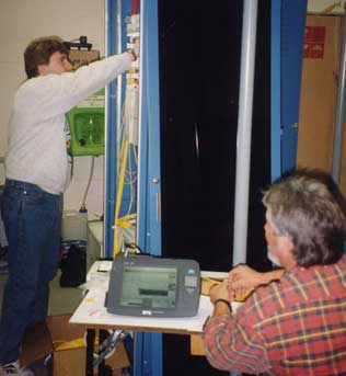
OTDRs
are an essential test tool for most OSP installation and restoration.
OTDRs are used during installation to check cable before installation
for shipping damage and after installation for damage caused by the
installation process. Each fiber splice is checked by an OTDR before
the splice is placed in a splice tray and the closure is sealed. After
a cable run is concatenated, the OTDR will inspect the complete cable
and every fiber in it and keep a record of the cable for future
reference in case of changes in the network or comparison for
restoration. During restoration, OTDRs can be used to locate problems
like a cable cut or compare the current data to the installed data for
comparison and determination of problems.
OTDRs are fiber optic instruments that can take a snapshot of a fiber, showing the location of splices, connectors, faults, etc. OTDRs are powerful test instruments for fiber optic cable plants, if one understands how to properly set the instrument up for the test and interpret the results. When used by a skillful operator, OTDRs can locate faults, measure cable length and verify splice loss. Within limits, they can also measure the loss of a cable plant. About the only fiber optic parameters they don't measure is optical power at the transmitter or receiver. There is a lot of information in the OTDR trace, as shown in the actual trace below.
OTDRs are fiber optic instruments that can take a snapshot of a fiber, showing the location of splices, connectors, faults, etc. OTDRs are powerful test instruments for fiber optic cable plants, if one understands how to properly set the instrument up for the test and interpret the results. When used by a skillful operator, OTDRs can locate faults, measure cable length and verify splice loss. Within limits, they can also measure the loss of a cable plant. About the only fiber optic parameters they don't measure is optical power at the transmitter or receiver. There is a lot of information in the OTDR trace, as shown in the actual trace below.
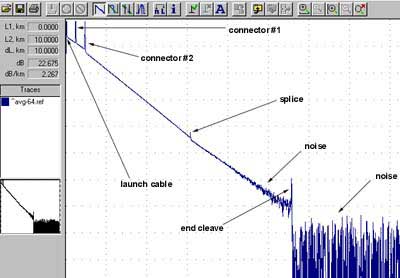
OTDRs
are almost always used on outside plant cables to verify the loss of
each splice as it is made and find stress points or damage caused by
installation. They are also widely used as OSP troubleshooting tools
since they can pinpoint problem areas such as loss caused by stress
placed on a cable during installation. Most ODTRs lack the distance
resolution for use on the shorter cables typical of premises networks.
OTDRs are available in versions for standardized fiber optic systems, singlemode or multimode, at the appropriate wavelengths. In order to use an OTDR properly, it's necessary to understand how it works, how to set the instrument up properly and how to analyze traces. OTDRs offer an "auto testing" option, but using that option without understanding the OTDR and manually checking its work often leads to problems.
OTDRs are available in versions for standardized fiber optic systems, singlemode or multimode, at the appropriate wavelengths. In order to use an OTDR properly, it's necessary to understand how it works, how to set the instrument up properly and how to analyze traces. OTDRs offer an "auto testing" option, but using that option without understanding the OTDR and manually checking its work often leads to problems.
(Read more about the OTDR)
How OTDRs Work Unlike sources and power meters which measure the loss of the fiber optic cable plant directly, the OTDR works indirectly. The source and meter duplicate the transmitter and receiver of the fiber optic transmission link, so the measurement correlates well with actual system loss.
The OTDR, however, uses backscattered light of the fiber to imply loss. The OTDR works like RADAR, sending a high power laser light pulse down the fiber and looking for return signals from backscattered light in the fiber itself or reflected light from connector or splice interfaces.
At any point in time, the light the OTDR sees is the light scattered from the pulse passing through a region of the fiber. Only a small amount of light is scattered back toward the OTDR, but with wider test pulses, sensitive receivers and signal averaging, it is possible to make measurements over relatively long distances. Since it is possible to calibrate the speed of the pulse as it passes down the fiber, the OTDR can measure time, calculate the pulse position in the fiber and correlate what it sees in backscattered light with an actual location in the fiber. Thus it can create a display of the amount of backscattered light at any point in the fiber.
Since the pulse is attenuated in the fiber as it passes along
the fiber and suffers loss in connectors and splices, the amount
of power in the test pulse decreases as it passes along the fiber
in the cable plant under test. Thus the portion of the light
being backscattered will be reduced accordingly, producing a
picture of the actual loss occurring in the fiber. Some calculations
are necessary to convert this information into a display, since
the process occurs twice, once going out from the OTDR and once
on the return path from the scattering at the test pulse.
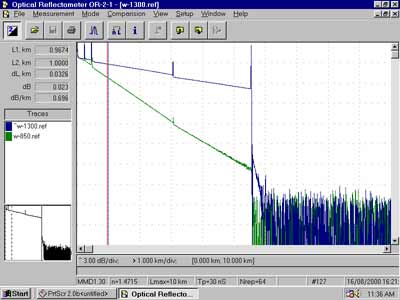 Actual OTDR Trace
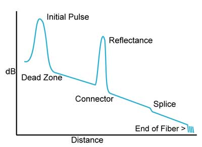 Diagram of OTDR trace with events shown
There is a lot of information
in an OTDR display. The slope of the fiber trace shows the attenuation
coefficient of the fiber and is calibrated in dB/km by the OTDR.
In order to measure fiber attenuation, you need a fairly long
length of fiber with no distortions on either end from the OTDR
resolution or overloading due to large reflections. If the fiber
looks nonlinear at either end, especially near a reflective event
like a connector, avoid that section when measuring loss.
Note the large initial pulse on the OTDR trace. That is caused by the high-powered test pulse reflecting off the OTDR connector and overloading the OTDR receiver. The recovery of the receiver causes the "dead zone" near the OTDR. To avoid problems caused by the dead zone, always use a launch cable of sufficient length when testing cables.
Note the large initial pulse on the OTDR trace. That is caused by the high-powered test pulse reflecting off the OTDR connector and overloading the OTDR receiver. The recovery of the receiver causes the "dead zone" near the OTDR. To avoid problems caused by the dead zone, always use a launch cable of sufficient length when testing cables.
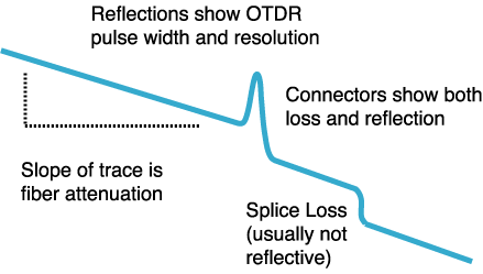
Connectors and splices are called "events" in OTDR
jargon. Both should show a loss, but connectors and mechanical
splices will also show a reflective peak so you can distinguish
them from fusion splices. Also, the height of that peak will
indicate the amount of reflection at the event, unless it is
so large that it saturates the OTDR receiver. Then peak will
have a flat top and tail on the far end, indicating the receiver
was overloaded. The width of the peak shows the distance resolution
of the OTDR, or how close it can detect events.
OTDRs can also detect problems
in the cable caused during installation. If a fiber is broken,
it will show up as the end of the fiber much shorter than the
cable or a high loss splice at the wrong place. If excessive
stress is placed on the cable due to kinking or too tight a bend
radius, it will look like a splice at the wrong location.
Making Measurements With The OTDRAll OTDRs display the trace on a screen and provide two or more markers to place at points on the screen to measure loss and distance. This can be used for measuring loss of a length of fiber, where the OTDR will calculate the attenuation coefficient of the fiber, or the loss of a connector or splice.
Fiber Attenuation Coefficient
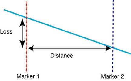
To
measure the length and attenuation of the fiber, we place the markers
on either end of the section of fiber we wish to measure. The OTDR will
calculate the distance difference between the two markers and give the
distance. It will also read the difference between the power levels of
the two points where the markers cross the trace and calculate the
loss, or difference in the two power levels in dB. Finally, it will
calculate the attenuation coefficient of the fiber by dividing loss by
distance and present the result in dB/km, the normal units for
attenuation. If the fiber segment is noisy or does not look straight,
the OTDR can average the measurement with a method called least squares
analysis (LSA).
Splice or Connector Loss
Splice or Connector Loss
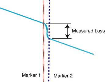
The
OTDR measures distance to the event and loss at an event - a connector
or splice - between the two markers. To measure splice loss, move the
two markers close to the splice to be measured, having each about the
same distance from the center of the splice. The OTDR will calculate
the dB loss between the two markers, giving you a loss reading in dB.
Measurements of connector loss or splices with some reflectance will
look very similar, except you will see a peak at the connector, caused
by the back reflection of the connector.
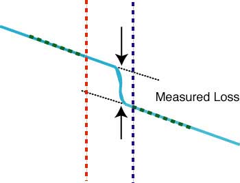
The OTDR can also use a least squares method to reduce noise effects and remove the error caused by the loss of the fiber between the two markers. The OTDR fits a line to the fibers on each side of the splice or connector and looks at the dB offset to measure loss.
Reflectance
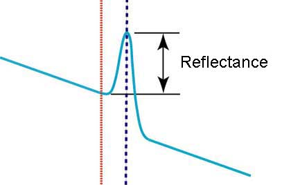
To
measure reflectance, the OTDR measures the amount of light that's
returned from both backscatter in the fiber and reflected from a
connector or splice. Calculating reflectance is a complicated process
involving the baseline noise of the OTDR, backscatter level and power
in the reflected peak. Like all backscatter measurements, it has a
fairly high measurement uncertainty, but an OTDR has the advantage of
showing where reflective events are located so they can be corrected if
necessary.
Comparing Traces
Comparing Traces
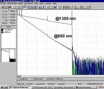
Comparing
two traces in the same window is useful for confirming data collection
and contrasting different test methods on the same fiber. Comparisons
are also used to compare fiber traces during troubleshooting or
restoration with traces take just after installation to see what has
changed. All OTDRs offer this feature, where you can copy one trace and
paste it on another to compare them.
OTDR Measurement UncertaintyLike all instruments, OTDRs cannot measure with perfect accuracy. Some of the measurement uncertainty with OTDRs is due to what is actually being measured. For example, when measuring the length of a fiber optic cable or the distance to a fault, the OTDR measures time and calculates distance based on the speed of light in the fiber or inversely the index of refraction of the fiber which determines the speed. Not all fibers have the same index of refraction, depending on the type of fiber and the manufacturer, and it is usually different for different wavelengths.
Group Index of Refraction (IOR) – Single Mode Fiber
| Manufacturer , | IOR @ 1310nm , | IOR @ 1550nm |
| Lucent Std. Single Mode, | 1.468, | 1.468 |
| Lucent TrueWave and TrueWave-RS, | 1.471, | 1.470 |
| Lucent AllWave, | 1.466, | 1.467 |
| Corning SMF-28, | 1.4675, | 1.4681 |
| Corning SMF-LS, | 1.471, | 1.470 |
| Corning E-LEAF, | N/A, | 1.469 |
| Alcatel SMOF, | 1.464, | 1.4645 |
The difference is only about 0.5% between the highest and lowest index of refraction, but that can mean an difference of 50 meters at 10 km, a significant error if one is trying to locate a fault.
The other problem with OTDR distance measurements is the difference between fiber length and cable length. Fiber is loosely fitted in buffer tubes and the buffer tubes are helically wound around the cable so the fiber will not be stressed when the cable is pulled.
But with this cable construction, the fiber length is about 1% longer than the cable length, a difference of 100 meters at 10 km. Since the OTDR measures fiber length, not cable length, this provides another error in measuring cable length, distance to an event like a splice or locating events in a long cable run.
If the actual cable length is known, and it can sometimes be read off the cable jacket or might have been recorded in the documentation when the cable was installed, one can use that to calibrate OTDR distances to actual cable distance. If OTDR traces are taken from both ends of a cable to an event or a fault, the relative distance to the event or fault can be estimated by using the ratio of the two measurements.
The biggest source of measurement uncertainty that occurs when testing with an OTDR is a function of the backscatter coefficient of the fibers being tested, the amount of light from the outgoing test pulse that is scattered back toward the OTDR. The backscattered light used for measurement is not a constant, but a function of the attenuation of the fiber and the diameter of the core of the fiber.
If you look at two different fibers spliced or connected together in an OTDR, any difference in backscatter from each fiber is a major source of error. If both fibers are identical, such as splicing a broken fiber back together, the backscattering will be the same on both sides of the joint, so the OTDR will measure the actual splice loss. However, if the fibers are different, unequal backscatter coefficients will cause a different percentage of light to be sent back to the OTDR.
If the fiber nearer the OTDR has more scattering (shown in the OTDR trace as attenuation) than the one after the connection, the percentage of light scattered back to the OTDR from the test pulse will go down, so the measured loss on the OTDR will include the actual loss plus a loss error caused by the lower backscatter level, making the displayed loss greater than it actually is. Looking the opposite way, from a low attenuation fiber to a high attenuation fiber, we find the backscatter goes up, making the measured loss less than it actually is. In fact, if the change in backscatter is greater than the splice loss, this shows a gain, a major confusion to new OTDR users.
While this error source is always present, it can be practically eliminated by taking readings both directions and averaging the measurements, and many OTDRs have this programmed in their measurement routines. This is the only way to test inline splices for loss and get accurate results.
OTDR "Ghosts"
If you are testing short cables with highly reflective connectors, you will likely encounter ghosts. These are caused by the reflected light from the far end connector reflecting back and forth in the fiber until it is attenuated to the noise level. Ghosts are very confusing, as they seem to be real reflective events like connectors, but will not show any loss. The best way to determine is a reflection is real or a ghost is to compare it to cable plant documentation. You can eliminate ghosts by reducing the reflections, for example using index matching fluid on the end of the launch cable.
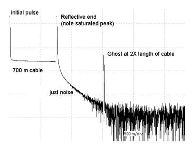
OTDR Limitations
The limited distance resolution of the OTDR makes it very hard to use in a LAN or building environment where cables are usually only a few hundred meters long. The OTDR has a great deal of difficulty resolving features in the short cables of a LAN and is likely to show "ghosts" from reflections at connectors, more often than not simply confusing the user.
Using The OTDR CorrectlyWhen
using an OTDR, there are a few cautions that will make testing easier
and more understandable. Always use a long launch cable, which allows
the OTDR to settle down after the initial pulse and provides a
reference cable for testing the first connector on the cable. If
testing the final connector on the cable is desired, a receive cable on
the far end of the cable plant is required.
The OTDR operator must carefully set up the instrument for each cable. Again, good documentation will help setting up the test parameters. Always start with the OTDR set for the shortest pulse width for best resolution and a range at least 2 times the length of the cable you are testing. Make an initial trace and see how you need to change the test parameters to get better results. Some users are tempted to use the OTDR’s autotest function. More problems are caused by novices using autotest than any other issue in using OTDRs. Never use autotest until a knowledgeable technician has set up the OTDR properly and verified that autotest gives acceptable results.
The OTDR operator must carefully set up the instrument for each cable. Again, good documentation will help setting up the test parameters. Always start with the OTDR set for the shortest pulse width for best resolution and a range at least 2 times the length of the cable you are testing. Make an initial trace and see how you need to change the test parameters to get better results. Some users are tempted to use the OTDR’s autotest function. More problems are caused by novices using autotest than any other issue in using OTDRs. Never use autotest until a knowledgeable technician has set up the OTDR properly and verified that autotest gives acceptable results.
Testing Long Haul, High Speed Fiber Optic Networks:
Chromatic Dispersion, Polarization Mode Dispersion and Spectral AttenuationOne of the big advantages of fiber optics is its capability for long distance high speed communications. Attenuation at long wavelengths is lower. Singlemode fiber has extremely high bandwidth. Fibers can be fusion spliced with virtually no loss. High-powered lasers and fiber amplifier regenerators mean long distances are easily obtained.
However over very long distances, new factors in fiber performance become important. Chromatic dispersion, the dispersion caused by light of different wavelengths, and polarization mode dispersion, caused by the polarization in fibers, become factors limiting fiber links. Even the variation of fiber attenuation with wavelength can become an issue when networks using wavelength-division multiplexing are implemented. All 3 factors may need testing on long distance networks to ensure proper link performance. (See the page on fiber for descriptions of these fiber characteristics.)
Chromatic Dispersion (CD) in the Cable PlantAs with any other component, optical fiber performance parameters can vary from batch to batch, so a long concatenated cable plant with many different fibers will have a end-to-end chromatic dispersion which is an integration of the CD of all the individual fibers. Therefore fiber in long distance links will probably be tested for CD after installation or before upgrading a link to higher bit rate electronics.
Testing Chromatic DispersionThere are several methods used for testing CD in fibers. All involve testing at a variety of wavelengths using several discrete sources of various wavelengths, a tunable laser or a broadband source with a monochromator in the receiver and measuring the relative speeds of the signals. The data taken at discrete wavelengths is then analyzed to calculate the dispersion in terms of ps/nm/km.
Test methods use phase delay or time of flight and generally require access to both ends of the fiber as well as a second fiber for synchronization of the two test instruments at either end. However, an OTDR test method is also used, since the OTDR measures time to convert to distance. Since the speed of light is different at various wavelengths, the OTDR would measure different distances on the same fiber at different wavelengths. Traces are taken at several discrete wavelengths and CD can be calculated from the difference in the distance data (or round trip time of the test pulse) obtained from the traces. This allows CD testing in the field from one end of the fiber.
All these methods have international standards for the test methods, instruments and data analysis.
| Standards | Description |
| IEC 60793-1-42 | Measurement methods and test procedures—chromatic dispersion |
| ITU-T G.650.1 | Definitions and test methods for linear, deterministic attributes of singlemode fiber and cable |
| TIA FOTP-175-B | Chromatic dispersion measurement of single-mode optical fibers |
| GR-761-CORE | Generic criteria for chromatic dispersion test sets |
Phase Shift Method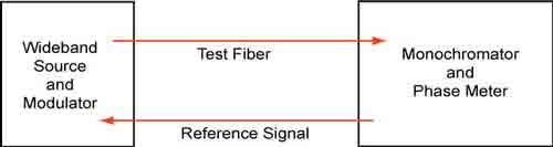
Pulse Delay Method
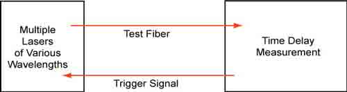
OTDR Test Method
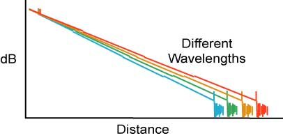
Pulse Delay Method
OTDR Test Method
Testing Polarization Mode Dispersion (PMD)
PMD is generally tested for fibers during manufacture or when being cabled. In the field, it is common to test PMD on newly installed fibers which are intended for operation at high speeds, generally above 2.5 Gb/s or when upgrading fibers installed some time in the past. Since PMD varies over time, a single test becomes an average and tests at a later time may be done for comparison.
There are a number of commonly used test methods for PMD, some of which are limited to the manufacturing environment, while others can be used in the field. Essentially, all the test instruments have a source which can vary the polarization of the test signal and a measurement unit that can analyze polarization changes.
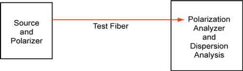
Here are descriptions of the methods and relevant standards.
PMD is generally tested for fibers during manufacture or when being cabled. In the field, it is common to test PMD on newly installed fibers which are intended for operation at high speeds, generally above 2.5 Gb/s or when upgrading fibers installed some time in the past. Since PMD varies over time, a single test becomes an average and tests at a later time may be done for comparison.
There are a number of commonly used test methods for PMD, some of which are limited to the manufacturing environment, while others can be used in the field. Essentially, all the test instruments have a source which can vary the polarization of the test signal and a measurement unit that can analyze polarization changes.
Here are descriptions of the methods and relevant standards.
| Description | Test Method | Standards |
| PMD for single-mode optical fibers by the Fixed Analyzer method | Extrema Counting (EC) Fourier Transform (FT) | FOTP-113 |
| PMD measurement for single-mode optical fibers by Stokes parameter measurements | Jones Matrix Eigen-analysis (JME) Poincaré Sphere Analysis (PSA) | FOTP-122 |
| PMD measurement for single-mode optical fibers and cable assemblies by Interferometry | Traditional Interferometry(TINTY) General Interferometry (GINTY) | FOTP-124 |
| Guideline for PMD and DGD measurement in single-mode fiber optic components and devices | | FOTP-196 |
| Measurement methods and test procedures—polarization mode dispersion | Fixed Analyzer measurement method (EC / FT) Stokes evaluation method (JME / PSA) Interferometry method (TINTY) | IEC 60793-1-48 |
| Portable PMD test sets used for analyzing single-mode fiber | GR-2947-CORE | |
| Definitions and test methods for statistical and nonlinear attributes of single-mode fiber and cable | Stokes parameter evaluation technique (JME & PSA) State of Polarization method (SOP) Interferometric methods ( TINTY & GINTY) Fixed Analyzer technique (EC / FT / Cosine Fourier Analysis) | ITU-T G.650.2 |
PMD
testing is not an easy, reproducible, accurate test. The measurement
uncertainty can be as high as 10-20%, as shown by testing done within
international standards committees. These committees have concluded
that all these measurement techniques are permissible, that there are
factors in making these measurements that are not well understood, and
the methods of data analysis are not without question.
All this uncertainty of PMD measurements has the effect of making comparisons between tests and test methods difficult. Variations are particularly high on tests of older fiber links. Presentations of field have even shown that variations in PMD can be correlated to wind speed for aerial cables.
PMD testing needs to be done on long links but the data must be analyzed intelligently to be of real use.
Spectral AttenuationWith
the develoment of low water peak fibers, the possibility of
transmission from 1260 to 1675 nm has been considered. This results
from careful manufacturing of the fiber to reduce the water in the
fiber (in the form of OH- ions) that causes higher spectral attenuation
at around 1244 and 1383 nm.
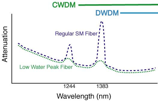
Since
one may want to use available fibers of unknown spectral attenuation
for CWDM which uses lasers from 1260 to 1670 nm in 20 nm windows, it
becomes necessary to test for spectral attenuation to verify the
usability. At the water peaks, legacy fibers may have attenuation
coefficients around 2 dB/km while low water peak fibers may be as low
as 0.4 dB/km.
Testing spectral attenuation is done per TIA/EIA-455-61 or IEC 61300-3-7 with broadband sources like LEDs and a spectrum analyzer on the receiving end of the fiber. Calibration is done with a short fiber length, the instrument calculates the spectral attenuation on a long length being tested. The measurement of spectral attenuation uses instruments similar to those used for CD testing by the phase shift method, so some instruments do both measurements at one time.
Testing spectral attenuation is done per TIA/EIA-455-61 or IEC 61300-3-7 with broadband sources like LEDs and a spectrum analyzer on the receiving end of the fiber. Calibration is done with a short fiber length, the instrument calculates the spectral attenuation on a long length being tested. The measurement of spectral attenuation uses instruments similar to those used for CD testing by the phase shift method, so some instruments do both measurements at one time.
Troubleshooting and Restoration
The time may come when you have to troubleshoot and fix the cable plant. If you have a critical application or lots of network cable, you should be ready to do it yourself. Smaller networks can rely on a contractor. If you plan to do it yourself, you need to have equipment ready (extra cables, mechanical splices, quick termination connectors, etc., plus test equipment.) and someone who knows how to use it.
We cannot emphasize more strongly the need to have good documentation on the cable plant. If you don't know where the cables go, how long they are or what they tested for loss, you will be spinning you wheels from the get-go. And you need tools to diagnose problems and fix them, and spares including a fusion splicer or some mechanical splices and spare cables. In fact, when you install cable, save the leftovers for restoration!
And the first thing you must decide is if the problem is with the cables or the equipment using it. A simple power meter can test sources for output and receivers for input and a visual tracer will check for fiber continuity. If the problem is in the cable plant, the OTDR is the next tool needed to locate the fault. More from FOA Tech Topics: Troubleshooting and Restoration
Getting Started in Fiber Optic Testing
Even if you're an experienced
installer, make sure you remember these things.
1. Have the right tools and test
equipment for the job.
- You will need:
- Source and power meter, optical loss test set (OLTS) or test kit with proper equipment adapters for the cable plant you are testing.
- Reference test cables that match the cables to be tested and mating adapters, including hybrids if needed
- Fiber Tracer or Visual Fault Locator
- Cleaning materials - lint free cleaning wipes and pure alcohol
- OTDR with launch and/or receive cables for outside plant jobs and troubleshooting
- Read more about fiber optic instruments below.
2. Know how to use your test
equipment
Before you start, get together all your tools and make sure they are all working properly and you and your installers know how to use them. It's hard to get the job done when you have to call the manufacturer from the job site on your cell phone to ask for help. Try all your equipment in the office before you take it into the field. Use it to test every one of your reference test jumper cables in both directions using the single-ended loss test to make sure they are all good. If your power meter has internal memory to record data be sure you know how to use this also. You can often customize these reports to your specific needs - figure all this out before you go it the field - it could save you time and on installations, time is money!
Before you start, get together all your tools and make sure they are all working properly and you and your installers know how to use them. It's hard to get the job done when you have to call the manufacturer from the job site on your cell phone to ask for help. Try all your equipment in the office before you take it into the field. Use it to test every one of your reference test jumper cables in both directions using the single-ended loss test to make sure they are all good. If your power meter has internal memory to record data be sure you know how to use this also. You can often customize these reports to your specific needs - figure all this out before you go it the field - it could save you time and on installations, time is money!
3. Know the network you're testing...
This is an important part of the documentation process we discussed earlier. Make sure you have cable layouts for every fiber you have to test and have calculated a loss budget so you know what test results to expect. Prepare a spreadsheet of all the cables and fibers before you go in the field and print a copy for recording your test data. You may record all your test data either by hand or if your meter has a memory feature, it will keep test results in on-board memory that can be printed or transferred to a computer when you return to the office.
This is an important part of the documentation process we discussed earlier. Make sure you have cable layouts for every fiber you have to test and have calculated a loss budget so you know what test results to expect. Prepare a spreadsheet of all the cables and fibers before you go in the field and print a copy for recording your test data. You may record all your test data either by hand or if your meter has a memory feature, it will keep test results in on-board memory that can be printed or transferred to a computer when you return to the office.
A note on using a fiber optic
source: eye safety.
Fiber optic sources, including test equipment, are generally too low in
power to cause any eye damage, but it's still advisable to check
connectors with a power meter before looking into it. Besides, most
fiber optic sources are at infrared wavelengths that are invisible to
the eye, making them more dangerous. Connector inspection microscopes
focus all the light into the eye and can increase the danger. Some
telco DWDM and CATV systems have very high power and they could be
harmful, so better safe than sorry. Read our page on Safety.
Outside Plant Fiber Optic Network Design
The Communications System
Cabling Design
Choosing Transmission Equipment
Planning The Route
Choosing Components
Cable Plant Link Loss Budget Analysis
Project Documentation
Planning for the Installation
Planning for Restoration
Managing A Fiber Optic Project
Fiber optic network design refers to the specialized processes leading to a successful installation and operation of a fiber optic network. It includes determining the type of communication system(s) which will be carried over the network, the geographic layout (premises, campus, outside plant (OSP, etc.), the transmission equipment required and the fiber network over which it will operate. Designing a fiber optic network usually also requires interfacing to other networks which may be connected over copper cabling and wireless.
Next to consider are requirements for permits, easements, permissions and inspections. Once we get to that stage, we can consider actual component selection, placement, installation practices, testing, troubleshooting and network equipment installation and startup. Finally, we have to consider documentation, maintenance and planning for restoration in event of a future outage.
The design of the network must precede not only the installation itself, but it must be completed to estimate the cost of the project and, for the contractor, bid on the job. Design not only affects the technical aspects of the installation, but the business aspects also.
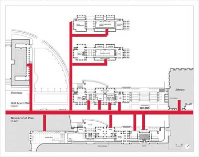 Campus network design
Working With Others
Designing a network requires working with other personnel involved in the project, even beyond the customer. These may include network engineers usually from IT (information technology) departments, architects and engineers overseeing a major project and contractors involved with building the projects. Other groups like engineers or designers involved in aspects of project design such as security, CATV or industrial system designers or specialized designers for premises cabling may also be overseeing various parts of a project that involves the design and installation of fiber optic cable plants and systems. Even company non-technical management may become involved when parts of the system are desired to be on exhibit to visitors.
Qualifications For Fiber Optic Network Designers
It’s the job of the designer to understand not only the technology of communications cabling, but also the technology of communications, and to keep abreast of the latest developments in not only the technology but the applications of both.
Designers should have an in-depth knowledge of fiber optic components and systems and installation processes as well as all applicable standards, codes and any other local regulations. They must also be familiar with most telecom technology (cabled or wireless), site surveys, local politics, codes and standards, and where to find experts in those fields when help is needed. Obviously, the fiber optic network designer must be familiar with electrical power systems, since the electronic hardware must be provided with high quality uninterruptible power at every location. And if they work for a contractor, estimating will be a very important issue, as that is where a profit or loss can be determined!
Those involved in fiber optic project design should already have a background in fiber optics, such as having completed a FOA CFOT certification course, and may have other training in the specialties of cable plant design and/or electrical contracting. It’s also very important to know how to find in-depth information, mostly on the web, about products, standards, codes and, for the OSP networks, how to use online mapping services like Google Maps. Experience with CAD systems is a definite plus.
Copper, Fiber or Wireless?
While discussions of which is better – copper, fiber or wireless – has enlivened cabling discussions for decades, it’s becoming moot. Communications technology and the end user market, it seems, have already made decisions that generally dictate the media and many networks combine all three. The designer of cabling networks, especially fiber optic networks, and their customers today generally have a pretty easy task deciding which media to use once the communications systems are chosen.
The Communications System
Before one can begin to design a fiber optic cable plant, one needs to establish with the end user or network owner where the network will be built and what communications signals it will carry. The contractor should be familiar with premises networks, where computer networks (LANs or local area networks) and security systems use structured cabling systems built around well-defined industry standards. Once the cabling exits a building, even for short links for example in a campus or metropolitan network, requirements for fiber and cable types change. Long distance links for telecommunications, CATV or utility networks have other, more stringent requirements, necessary to support longer high speed links, that must be considered.
But while the contractor generally considers the cabling requirements first, the real design starts with the communications system requirements established by the end user. One must first look at the types of equipment required for the communications systems, the speed of the network and the distances to be covered before considering anything related to the cable plant. The communications equipment will determine if fiber is necessary or preferable and what type of fiber is required.
Outside Plant Networks
Telephone networks are mainly outside plant (OSP) systems, connecting buildings over distances as short as a few hundred meters to hundreds or thousands of kilometers. Data rates for telecom are typically 2.5 to 10 gigabits per second using very high power lasers that operate exclusively over singlemode fibers. The big push for telecom is now taking fiber directly to a commercial building or the home, since the signals are now too fast for traditional twisted copper pairs.
CATV also uses singlemode fibers with systems that are either hybrid fiber-coax (HFC) or digital where the backbone is fiber and the connection to the home is on coax. Coax still works for CATV since it has very high bandwidth itself. Some CATV providers have discussed or even tried some fiber to the home, but have not seen the economics become attractive yet.
Besides telecom and CATV, there are many other OSP applications of fiber. Intelligent highways are dotted with security cameras and signs and/or signals connected on fiber. Security monitoring systems in large buildings like airports, government and commercial buildings, casinos, etc. are generally connected on fiber due to the long distances involved. Like other networks, premises applications are usually multimode while OSP is singlemode to support longer links.
Metropolitan networks owned and operated by cities can carry a variety of traffic, including surveillance cameras, emergency services, educational systems, telephone, LAN, security, traffic monitoring and control and sometimes even traffic for commercial interests using leased bandwidth on dark fibers or city-owned fibers. However, since most are designed to support longer links than premises or campus applications, singlemode is the fiber of choice.
For all except premises applications, fiber is the communications medium of choice, since its greater distance and bandwidth capabilities make it either the only choice or considerably less expensive than copper or wireless. Only inside buildings is there a choice to be made, and that choice is affected by economics, network architecture and the tradition of using copper inside buildings. Next, we’ll look at the fiber/copper/wireless choices in more detail.
Premises Networks
Premises cable systems are designed to carry computer networks based on Ethernet which currently may operate at speeds from 10 megabits per second to 10 gigabits per second. Other systems may carry security systems with digital or analog video, perimeter alarms or entry systems, which are usually low speeds, at least as far as fiber is concerned. Premises telephone systems can be carried on traditional twisted pair cables or, as is becoming more common, utilize LAN cabling with voice over IP (VoIP) technology.
Premises networks are usually short, often less than the 100 meters (about 330 feet) used as the limit for standardized structured cabling systems that allow twisted pair copper or fiber optic cabling, with backbones on campus networks used in industrial complexes or institutions as long as 500 m or more, requiring optical fiber.
Premises networks generally operate over multimode fiber. Multimode systems are less expensive than singlemode systems, not because the fiber is cheaper (it isn’t) nor because cable is cheaper (the same), but because the large core of multimode fiber allows the use of cheaper LED or VCSEL sources in transmitters, making the electronics much cheaper. Astute designers and end users often include both multimode and singlemode fibers in their backbone cables (called hybrid cables) since singlemode fibers are very inexpensive and it provides a virtually unlimited ability to expand the systems.
Premises networks will include a entrance facility where outside plant and premises communications systems meet. This facility must include not only cabling connections but compatible communications equipment. Since it is indoors, it must consider issues for building and electrical codes, such as the common requirement that bare OSP cables can only come 50 feet (about 15 meters) before being terminated in fire-rated cables unless it is in conduit.
Cabling Design
Long Distance and Outside Plant Cabling
Other than telco systems that still use copper for the final connection to the home, practically every cable in the telephone system is fiber optic. CATV companies use a high performance coax into the home, but it connects to a fiber optic backbone. The Internet backbone is all fiber. Most commercial buildings in populous areas have direct fiber connections from communications suppliers. Cities use SM fiber to connect municipal buildings, surveillance cameras, traffic signals and sometimes offer commercial and residential connections, all over singlemode fiber. Even cellular antenna towers along highways and on tall buildings usually have fiber connections. Remote areas such as central Africa depend on satellite communications since cables are too expensive to run long distances for the small amounts of traffic involved.
Designing long distance or outside plant applications generally means choosing cabling containing singlemode (SM) fiber over all other media. Most of these systems are designed to be used over distances and speeds that preclude anything but SM fiber. Occasionally other options may be more cost effective, for example if a company has two buildings on opposite sides of a highway, a line-of-sight or radio optical wireless network may be easier to use since they have lower cost of installation and are easier to obtain relevant permits.
The choice of the actual singlemode fiber, however, can depend on the application. Depending on the length of the link, the wavelength of the transmitters, data rate of the transmission and if CWDM or DWDM are planned, different types of fiber may be optimal. Refer to Chapter 5 on fiber for more details.
Premises Cabling
The desire for mobility, along with the expansion of connected services, appears to lead to a new type of corporate network. Fiber optic backbone with copper to the desktop where people want direct connections and multiple wireless access points, more than is common in the past, for full coverage and maintaining a reasonable number of users per access point is the new norm for corporate networks.
Most building management systems use proprietary copper cabling, for example thermostat wiring and paging/audio speaker systems. Security monitoring and entry systems, certainly the lower cost ones, still depend on coax copper cable, although high security facilities like government and military installations often pay the additional cost for fiber’s more secure nature.
Surveillance systems are becoming more prevalent in buildings, especially governmental, banking, or other buildings that are considered possible security risks. While coax connections are common in short links and structured cabling advocates say you can run cameras limited distances on Cat 5E or Cat 6 UPT like computer networks, fiber has become a much more common choice. Besides offering greater flexibility in camera placement because of its distance capability, fiber optic cabling is much smaller and lightweight, allowing easier installation, especially in older facilities like airports or large buildings that may have available spaces already filled with many generations of copper cabling.
When these premises communications systems connect to the outside world, it is generally to singlemode optical fiber. The entrance facility and equipment room must accommodate the equipment needed to make those connections.
Use of Cabling Standards
Many documents relating to cable plant design focus on industry standards for both communications systems and cable plants. US standards come from the TIA or Telcordia while worldwide standards may come from ISO/IEC or ITU.
It is important to realize why and by whom these standards are written. These standards are written by manufacturers of products to ensure that various manufacturers’ products work together properly. Whenever users specify standards for any project, it is important that the contractor/installer understand what standards are being referenced and ensure that such standards are relevant to the job being done.
Choosing Transmission Equipment
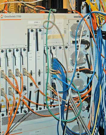 Choosing
transmission equipment is the next step in designing a fiber optic
network. This step will usually be a cooperative venture involving the
customer, who knows what kinds of data they need to communicate, the
designer and installer, and the manufacturers of transmission
equipment. Transmission equipment and the cable plant are tightly
interrelated. The distance and bandwidth will help determine the fiber
type necessary and that will dictate the optical interfaces on the
cable plant. The ease of choosing equipment may depend on the type of
communications equipment needed.
Choosing
transmission equipment is the next step in designing a fiber optic
network. This step will usually be a cooperative venture involving the
customer, who knows what kinds of data they need to communicate, the
designer and installer, and the manufacturers of transmission
equipment. Transmission equipment and the cable plant are tightly
interrelated. The distance and bandwidth will help determine the fiber
type necessary and that will dictate the optical interfaces on the
cable plant. The ease of choosing equipment may depend on the type of
communications equipment needed.Telecom has been standardized on fiber optics for 30 years now, so they have plenty of experience building and installing equipment. Since most telecom equipment uses industry conventions, you can usually find equipment for telecom transmission that will be available for short links (usually metropolitan networks, maybe up to 20-30 km), long distance and then really long distance like undersea runs. All run on singlemode fiber, but may specify different types of singlemode.
Shorter telecom links will use 1310 nm lasers on regular singlemode fiber, often referred to as G.652 fiber, it’s international standard. Longer links will use a dispersion-shifted fiber optimized for operation with 1550 nm lasers (G.652 fiber). For most applications, one of these will be used. Most telco equipment companies offer both options.
Most CATV links are AM (analog) systems based on special linear lasers called distributed feedback (DFB) lasers using either 1310 nm or 1550 nm operating on regular singlemode fibers. As CATV moves to digital transmission, it will use technology more like telecom, which is already all digital.
The choices become more complex when it comes to data and CCTV because the applications are so varied and standards may not exist. In addition, equipment may not be available with fiber optic transmission options, requiring conversion from copper ports to fiber using devices called media converters.
In computer networks, the Ethernet standards, created by the IEEE 802.3 committee, are fully standardized. You can read the standards and see how far each equipment option can transmit over different types of fiber, choosing the one that meets your needs. Most network hardware like switches or routers are available with optional fiber optic interfaces, but PCs generally only come with UTP copper interfaces that require media converters. An Internet search for “fiber optic media converters” will provide you with dozens of sources of these inexpensive devices. Media converters will also allow the choice of media appropriate for the customer application, allowing use with multimode or singlemode fiber and may even offer transceiver options for the distance that must be covered by the link.
CCTV is a similar application. More cameras now come with fiber interfaces since so many CCTV systems are in locations like big buildings, airports, or areas where the distances exceed the capability of coax transmission. If not, video media converters, usually available from the same vendors as the Ethernet media converters, are readily available and also inexpensive. Again, choose converters that meet the link requirements set by the customer application, which in the case of video, not only includes distance but also functions, as some video links carry control signals to the camera for camera pan, zoom and tilt in addition to video back to a central location.
What about industrial data links? Many factories use fiber optics for its immunity to electromagnetic interference. But industrial links may use proprietary means to send data converted from old copper standards like RS-232, the ancient serial interface once available on every PC, SCADA popular in the utility industry, or even simple relay closures. Many companies that build these control links offer fiber optic interfaces themselves in response to customer requests. Some of these links have been available for decades, as industrial applications were some of the first premises uses of fiber optics, dating back to before 1980.
Whatever the application, it’s important for the end user and the cabling contractor to discuss the actual application with the manufacturer of the transmission hardware to ensure getting the proper equipment. While the telecom and CATV applications are cut and dried and the data (Ethernet) applications covered by standards, it is our experience that not all manufacturers specify their products in exactly the same way.
One company in the industrial marketplace offered about fifteen different fiber optic products, mainly media converters for their control equipment. However, those fifteen products had been designed by at least a dozen different engineers, not all of whom were familiar with fiber optics and especially fiber jargon and specifications. As a result, one could not compare the products to make a choice or design them into a network based on specifications. Until their design, sales and applications engineers were trained in fiber optics and created guidelines for product applications, they suffered from continual problems in customer application.
The only way to make sure you are choosing the proper transmission equipment is to make absolutely certain the customer and equipment vendor – and you – are communicating clearly what you are planning to do.
Planning The Route
Having decided to use fiber optics and chosen equipment appropriate for the application, it’s time to determine exactly where the cable plant and hardware will be located. One thing to remember – every installation will be unique. The actual placement of the cable plant will be determined by the physical locations along the route, local building codes or laws and other individuals involved in the designs. As usual, premises and outside plant installations are different so we will consider them separately.
Premises and campus installations can be simpler since the physical area involved is smaller and the options fewer. Start with a good set of architectural drawings and, if possible, contact the architect, contractor and/or building manager. Having access to them means you have someone to ask for information and advice. Hopefully the drawings are available as CAD files so you can have a copy to do the network cabling design in your computer, which makes tweaking and documenting the design so much easier.
If the building is still in the design stage, you may have the opportunity to provide inputs on the needs of the cable plant. Ideally, that means you can influence the location of equipment rooms, routing of cable trays and conduits, availability of adequate conditioned power and separate data grounds, sufficient air-conditioning and other needs of the network. For pre-existing buildings, detailed architectural drawings will provide you with the ability to route cabling and network equipment around the obstacles invariably in your way.
Outside plant (OSP) cabling installations have enormous variety depending on the route the cable must take. The route may cross long lengths of open fields, run along paved rural or urban roads, cross roads, ravines, rivers or lakes, or, more likely, some combination of all of these. It could require buried cables, aerial cables or underwater cables. Cable may be in conduit, innerduct or direct buried, aerial cables may be self-supporting or lashed to a messenger. Longer runs often include crossing water, so the cable may be underwater or be lashed across a bridge with other cables.
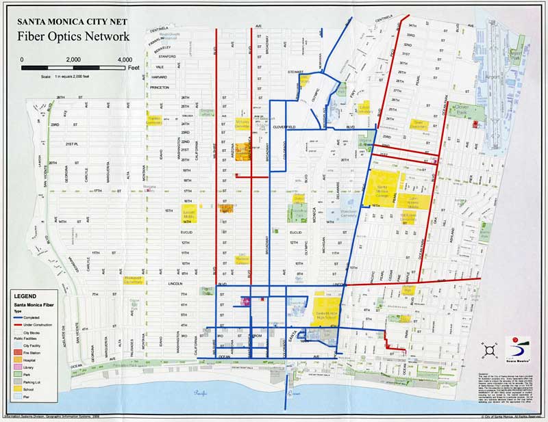
Site Visits
And as soon as possible, you must visit the site or route where the network will be installed. Outside plant routes need to be driven or walked every foot of the way to determine the best options for cable placement, obstacles to be avoided or overcome, and to determine what local entities may have input into the routing. Often cities or other governments will know of available conduits or rules on using utility poles that can save design time and effort.
For installations inside current buildings, you should inspect every area to be absolutely certain you know what the building really looks like and then mark up drawings to reflect reality, especially all obstacles to running cabling and hardware and walls requiring firestopping that are not on the current drawings. Take pictures if you can. For buildings under construction, a site visit is still a good idea, just to get a feeling of what the final structure will be like and to get to know the construction managers you will be working with. They may be the best source of information on who the local authorities are who will be inspecting your work and what they expect.
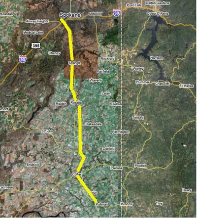 OSP network route on satellite mapWith
all those options on OSP installations, where do you start? With a good
map. Not just a road map or a topographical map, but satellite images
overlaid on roads is much better, like “Google Maps” can provide.
Creating a route map is the first step, noting other utilities along
the route on that map, and checking with groups that document the
current utilities to prevent contractors from damaging currently
installed pipes and cables.
OSP network route on satellite mapWith
all those options on OSP installations, where do you start? With a good
map. Not just a road map or a topographical map, but satellite images
overlaid on roads is much better, like “Google Maps” can provide.
Creating a route map is the first step, noting other utilities along
the route on that map, and checking with groups that document the
current utilities to prevent contractors from damaging currently
installed pipes and cables. Once you have marked up maps, the real “fun” begins: finding out whose permission you need to run your cabling. OSP installs are subject to approval by local, state and federal authorities who will influence heavily how your project is designed. Some cities, for example, ban aerial cables. Some have already buried conduit which you can use for specific routes. Since many municipalities have installed city-owned fiber networks, they may have fiber you can rent, rather than go through the hassle of installing your own.
Unless you are doing work for a utility that has someone who already has the contacts and hopefully easements needed, you may get to know a whole new set of people who have control over your activities. And you have to plan for adequate time to get approval from everyone who is involved.
Call Before You Dig
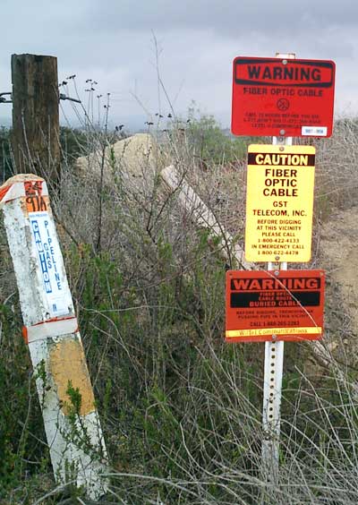
Digging safely is vitally important. The risk is not just interrupting communications, but the life-threatening risk of digging up high voltage or gas lines. Some obstacles may be found during site visits, where signs like these are visible. There are several services that maintain databases of the location of underground services that must be contacted before any digging occurs, but mapping these should be done during the design phase and double-checked before digging to ensure having the latest data.
If all this sounds vague, it is. Every project is different and requires some careful analysis of the conditions before even beginning to choose fiber optic components and plan the actual installation. Experience is the best teacher.
Choosing Components
Choosing Components For Outside Plant Installations
The choice of outside plant fiber optic (OSP) components begins with developing the route the cable plant will follow. Once the route is set, one knows where cables will be run, where splices are located and where the cables will be terminated. All that determines what choices must be made on cable type, hardware and sometimes installation methodology.
Cables
When choosing components, most projects start with the choice of a cable. Cable designs are optimized for the application type. In OSP installations, cables may be underground, direct buried, aerial or submarine (or simply underwater.)
Underground cables are generally installed in conduit which is usually a 4 inch (10 cm) conduit with several innerducts for pulling cables. Here cables are designed for high pulling tension and lubricants are used to reduce friction on longer pulls. Automated pulling equipment that limits pulling tension protects the cables. Very long runs or those with more bends in the conduit may need intermediate pulls where cable is pulled, figure-8ed and then pulled to the next stage or intermediate pulling equipment is used. Splices on underground cables are generally stored above ground in a pedestal or in a vault underground. Sufficient excess cable is needed to allow splicing in a controlled environment, usually a splicing trailer, and the storage of excess cable must be considered in the planning stage.
Direct buried cable is placed underground without conduit. Here the cable must be designed to withstand the rigors of being buried in dirt, so it is generally a more rugged cable, armored to prevent harm from rodent chewing or the pressures of dirt and rocks in which it is buried. Direct burial is generally limited to areas where the ground is mostly soil with few rocks down to the depth required so trenching or plowing in cable is easily accomplished. Splices on direct buried cables can be stored above ground in a pedestal or buried underground. Sufficient excess cable is needed to allow splicing in a controlled environment, usually a splicing trailer, and the storage of excess cable must be considered.
Aerial installations go from pole to pole, but the method of securing cables can vary depending on the situation. Some cables are lashed to messengers or other cables, such as CATV where light fiber cables are often lashed to the heavy coax already in place. Cables are available in a “8” configuration with an attached steel messenger that provides the strength to withstand tension on the cable. Some cables are made to directly be supported without a messenger, called all-dielectric sefl-supporting cables that use special hardware on poles to hold the cables. Optical ground wire is used by utilities for high voltage distribution lines. This cable is an electrical cable with fibers in the middle in a hermetically-sealed metal tube. It is installed just like standard electrical conductors. Splices on aerial cables can be supported on the cables or placed on poles or towers, Most splices are done on the ground, although it is sometimes done in a bucket or even on a tent supported on the pole or tower. Hardware is available for coiling and storing excess cable.
Sometime OSP installations involve running cables across rivers or lakes where other routes are not possible. Special cables are available for this that are more rugged and sealed. Even underwater splice hardware is available. Landings on the shore need to be planned to prevent damage, generally by burying the cable close to shore and marking the landing. Transoceanic links are similar but much more complex, requiring special ships designed for cable laying.
Since OSP applications often use significant lengths of cables, the cables can be made to order, allowing optimization for that particular installation. This usually allows saving costs but requires more knowledge on the part of the user and more time to negotiate with several cable manufacturers.
To begin specifying the cable, one must know how many fibers of what type will be included in each cable. It’s important to realize that fiber, especially singlemode fiber used in virtually all OSP installations, is cheap and installation is expensive. Installation of an OSP cable may cost a hundred times the cost of the cable itself. Choosing a singlemode fiber is easy, with basic 1300 nm singlemode (called G.652 fiber) adequate for all but the longest links or those using wavelength-division multiplexing. Those may need special fiber optimized at 1500-1600 nm (G.653 or G.654). For premises and campus cable plants, OM3 type laser-optimized 50/125 multimode fiber is probably the best choice for any multimode OSP runs, as its lower attenuation and higher bandwidth will make most networks work better.
Including more fibers in a cable will not increase the cable cost proportionally; the basic cost of making a cable is fixed but adding fibers will not increase the cost much at all. Choosing a standard design will help reduce costs too, as manufacturers may have the cable in stock or be able to make your cable at the same time as others of similar design. The only real cost for adding more fibers is additional splicing and termination costs, still small with respect to total installed cost. And remember that having additional fibers for future expansion, backup systems or in case of breaks involving individual fibers can save many future headaches.
Common traits of all outside plant cables include strength and water or moisture protection. The necessary strength of the cable will depend on the installation method (see below.) All cables installed outdoors must be rated for moisture and water resistance. Until recently, most people chose a gel-filled cable, but now dry-water blocked cables are widely available and preferred by many users. These cables use water-absorbing tape and power that expands and seals the cable if any water enters the cable. Installers especially prefer the dry cables as it does not require the messy, tedious removal of the gel used in many cables, greatly reducing cable preparation for splicing or termination.
OSP cable construction types are specifically designed for strength depending on where they are to be direct buried, buried in conduit, placed underwater or run aerially on poles. The proper type must be chosen for the cable runs. Some applications may even use several types of cable. Having good construction plans will help in working with cable manufacturers to find the appropriate cable types and ordering sufficient quantities. One must always order more cable than route lengths, to allow for service loops, preparation for termination and excess to save for possible restoration needs in the future.
Like cable types, cable plant hardware types are quite diverse and should be chosen to match the application type and cable types being used. With so many choices in hardware, working with cable manufacturers is the most expeditious way to chose hardware and ensure compatibility. Besides cable compatibility, the hardware must be appropriate for the location, which can be outdoors, hung on poles, buried, underwater, inside pedestals, vaults or buildings, etc. Sometimes the hardware will need to be compatible with local zoning, for example in subdivisions or business parks. The time consumed in choosing this hardware can be lengthy, but is very important for the long term reliability of the cable plant.
Splicing And Termination Hardware
Splicing and termination are the final category of components to be chosen. Most OSP singlemode fiber is fusion spliced for low loss, low reflectance and reliability. Multimode fiber, especially OM2, 3 and 4, is also easily fusion spliced, but if only a few splices are necessary, mechanical splicing may provide adequate performance and reliability.
Finished splices are placed in a splice tray and placed in a splice closure outdoors or optionally in trays on patch panels indoors. They are sealed to prevent moisture reaching the splices and are designed to be re-entered for repair or re-routing fibers. Splice closures are available in hundreds of designs, depending on the placement of the closure, for example underground in a manhole or vault, above ground in a pedestal, buried underground or mounted on a pole. Closures must also be chosen by the number and types of cables being spliced and whether they enter at both ends or only one. The numbers of cables and splices that a closure can accommodate will determine the size of the closure, and those for high fiber count cables can get quite large.
Splice trays generally hold twelve single fiber fusion splices but may hold fewer ribbon or mechanical splices. Each splice tray should securely hold the splice and have a cover to protect the fibers when stacked in the closure.
Singlemode fibers are best terminated by fusion spicing factory-made pigtails onto fibers in the cable and protecting the splices in a closure or patch panel tray. If termination is done directly on multimode OSP cables, breakout kits will be necessary to sleeve fibers for reliability when connectors are directly attached. This takes more installation time than splicing pre-terminated pigtails on the cables, as is common with singlemode fiber cables, and may not save any costs. Even complete preterminated outside cable plant systems are becoming available, reducing the time necessary for termination and splicing. Talk to the cable manufacturers to determine feasibility of this option.
Outdoor terminations are sometimes housed in pedestals or equipment housings such as those used for local phone switches or traffic control systems. Some of these closures may not be fully sealed from dust and moisture, in which case it is recommended that the fiber connections be inside a more protective housing to prevent future unreliability.
Choosing the proper components for OSP installations can take time, but is important for system operation. Once components are chosen, the materials lists are added to the documentation for purchase, installation and future reference.
Choosing Components For Premises Installations
Premises cabling and outside plant cabling will coexist in the entrance facility or the equipment room where the two are connected. The choice of premises fiber optic components are affected by several factors, including the choice of communications equipment, physical routing of the cable plant and building codes and regulations. If the design is a corporate network (LAN), the design will probably include a fiber optic backbone connecting computer rooms to wiring closets. The wiring closets house switches that convert the fiber backbone to UTP copper for cable connected desktops and either copper or fiber to wireless access points. Some desktops, especially in engineering or design departments, may require fiber to the desktop for it’s greater bandwidth. Extra cables or fibers may be needed for security systems (alarms, access systems or CCTV cameras) and building management systems also.
Design of the fiber optic cable plant requires coordinating with everyone who is involved in the network in any way, including IT personnel, company management, architects and engineers, etc. to ensure all cabling requirements are considered at one time, to allow sharing resources.
As in OSP design, consider the fiber choice first. Most premises networks use multimode fiber, but many users now install hybrid cables with singlemode fibers for future expansion. The 62.5/125 micron fiber (OM1 fiber) that has been used for almost two decades has mostly been superceded by the new 50/125 laser-optimized fiber (OM3), as it offers substantial bandwidth/distance advantages.
Virtually all equipment will operate over 50/125 OM3 fiber just as well as it did on 62.5/125 OM1 fiber, but it’s always a good idea to check with the equipment manufacturers to be sure. Remember in the design documentation to include directions to mark all cables and patchpanels with aqua-colored tags, indicative of OM3 fiber.
Cable in premises applications is generally either distribution or breakout cable. Distribution cables have more fibers in a smaller diameter cable, but require termination inside patch panels or wall mounted boxes. Breakout cables are bulky, but they allow direct connection without hardware, making them convenient for industrial use. Fiber count can be an issue, as backbone cables now have many fibers for current use, future expansion and spares, making distribution cables the more popular choice. The cable jacket must be fire-retardant per the NEC, generally OFNR-rated (Riser) unless the cable in air-handling areas above ceilings, where OFNP (plenum) is needed. Cable jacket color for OM3 cables can be ordered in aqua for identification as both fiber optics and OM3 50/125 fibers.
If the cable is going to be run between buildings, indoor/outdoor designs are now available that have dry water-blocking and a double jacket. The outer jacket is moisture-resistant for outdoor use but can be easily stripped, leaving the fire-rated inner jacket for indoor runs.
Fiber optic connector choices are also changing. STs and even SCs are succumbing to the success of the smaller LC connector. Since most fast (gigabit and above) equipment uses LC connectors, using them in the cable plant means only one connector needs to be supported. The LC offers another big advantage for those users who are upgrading to OM3 fiber. The LC connector is incompatible with SC and ST connectors, so using it on 50/125 fiber cable plants prevents mixing 50 and 62.5 fibers with high fiber mismatch losses.
Premises fiber optic cables need to be run separately from copper cables to prevent crushing. Sometimes they are hung carefully below copper cable trays or pulled in innerduct. Using innerduct can save installation time, since the duct (which can be purchased with pull tapes already inside) can be installed quickly without fear of damage and then the fiber optic cable pulled quickly and easily. Some applications may require installing fiber optic cables inside conduit, which requires care to minimize bends, provide intermediate pulls to limit pulling force or use fiber optic cable lubricants.
The hardware necessary for the installation will need to be chosen based on where the cables are terminated. Premises runs are generally point-to-point and are not spliced. Wherever possible, allow room for large radii in the patch panels or wall-mounted boxes to minimize stress on the fibers. Choose hardware that is easy to enter for moves, adds and changes but lockable to prevent intrusion.
In premises applications, it’s worth considering a preterminated system. These use backbone cables terminated in multifiber connectors and preterminated patch panel modules. If the facility layout is properly designed, the cable manufacturer can work with you to create a “plug and play” system that needs no on-site termination and the cost may be very competitive to a field-terminated system.
Creating A Materials List
For every installation, a complete materials list must be created listing each component needed and quantities required. This list will be used by the installation crew, but first it will be used to estimate the cost of the project.
It is very important to list every component. Some components can be estimated based on other quantities. Ducts for example will be ordered in lengths similar to the cable pulled into them. Each fiber needs termination on both ends of the cable plant. Splice trays and closures must be ordered according to the numbers of fibers in the cables.
You should include extra quantities for installation. Every splice point, for example, needs 10-20 meters extra cable for splicing in a splice trailer, stripping for the splice and service loops. Extra cable should also be ordered to be kept for possible future restoration. Extra connectors or pigtails are needed to replace those improperly installed during installation. Some contractors routinely order 2-5% more than they estimate is necessary for the job.
While ordering more components than necessary can be costly, it’s less expensive than being short during the actual installation, especially for special order items like cables or patchcords. Excess components should be packed and stored as part of a restoration kit.
Cable Plant Link Loss Budget Analysis
Loss budget analysis is the calculation and verification of a fiber optic system's operating characteristics. This encompasses items such as routing, electronics, wavelengths, fiber type, and circuit length. Attenuation and bandwidth are the key parameters for budget loss analysis. The designer should analyze link loss early in the design stage prior to installing a fiber optic system to make certain the system will work over the proposed cable plant.
Both the passive and active components of the circuit can be included in the budget loss calculation. Passive loss is made up of fiber loss, connector loss, and splice loss. Don't forget any couplers or splitters in the link. If the system electronics are already chosen, active components such as wavelength, transmitter power, receiver sensitivity, and dynamic range can be considered. If the electronics are not known, industry generic or standard loss values can be used for the loss budget. Prior to system turn up, test the insertion loss of the cable plant with a source and power meter to ensure that it is within the loss budget.
The idea of a loss budget is to insure the network equipment will work over the installed fiber optic link. It is normal to be conservative over the specifications. Don't use the best possible specs for fiber attenuation or connector loss to allow some margin for installation and component degradation over time.
The best way to illustrate calculating a loss budget is to show how it's done for a typical cable plant, here a 2 km hybrid multimode/singlemode link with 5 connections (2 connectors at each end and 3 connections at patch panels in the link) and one splice in the middle. See the drawings below of the link layout and the instantaneous power in the link at any point along it's length, scaled exactly to the link drawing above it.
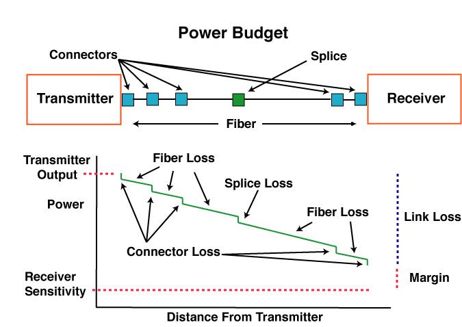
Cable Plant Passive Component Loss
Step 1. Calculate fiber loss at the operating wavelengths (length times standard estimates of loss at each wavelength)
| Cable Length (km) | 2.0 | 2.0 | 2.0 | 2.0 |
| Fiber Type | Multimode | Singlemode | ||
| Wavelength (nm) | 850 | 1300 | 1300 | 1550 |
| Fiber Atten. (dB/km) | 3 [3.5] | 1 [1.5] | 0.4 [1/0.5] | 0.3 [1/0.5] |
| Total Fiber Loss (dB) | 6.0 [7.0] | 2.0 [3.0] | 0.8 [2/1 | 0.6 [2/1] |
(All specifications in brackets are maximum values per EIA/TIA 568 standard. For singlemode fiber, a higher loss is allowed for premises applications, 1 dB/km for premises, 0.5 dB/km for outside plant. )
Step 2. Connector Loss
Multimode connectors will have losses of 0.2-0.5 dB typically. Singlemode connectors, which are factory made and fusion spliced on will have losses of 0.1-0.2 dB. Field terminated singlemode connectors may have losses as high as 0.5-1.0 dB. Let's calculate it at both typical and worst case values.
| Connector Loss | 0.3 dB (typical adhesive/polish connector) | 0.75 dB (prepolished/splice connector and TIA-568 max acceptable) |
| Total # of Connectors | 5 | 5 |
| Total Connector Loss | 1.5 dB | 3.75 dB |
(All connectors are allowed 0.75 max per EIA/TIA 568 standard)
Many designers and technicians forget when doing a loss budget that the connectors on the end of the cable plant must be included in the loss budget. When the cable plant is tested, the reference cables will mate with those connectors and their loss will be included in the measurements.
Step 3. Splice Loss
Multimode splices are usually made with mechanical splices, although some fusion splicing is used. The larger core and multiple layers make fusion splicing abut the same loss as mechanical splicing, but fusion is more reliable in adverse environments. Figure 0.1-0.5 dB for multimode splices, 0.3 being a good average for an experienced installer. Fusion splicing of singlemode fiber will typically have less than 0.05 dB (that's right, less than a tenth of a dB!)
| Splice Loss | 0.3 dB |
| Total # splices | 1 |
| Total Splice Loss | 0.3 dB |
(For this loss budget calculation, all splices are allowed 0.3 max per EIA/TIA 568 standard)
Step 4. Total Cable Plant Loss
Add together the fiber, connector and splice losses to get the total link loss of the cable plant.
| Best Case [TIA 568 Max] | | Best Case [TIA 568 Max] | | |
| Wavelength (nm) | 850 | 1300 | 1300 | 1550 |
| Total Fiber Loss (dB) | 6.0 [7.0] | 2.0 [3.0] | 0.8 [2/1] | 0.6 [2/1] |
| Total Connector Loss (dB) | 1.5 [3.75] | 1.5 [3.75] | 1.5 [3.75] | 1.5 [3.75] |
| Total Splice Loss (dB) | 0.3 [0.3] | 0.3 [0.3] | 0.3 [0.3] | 0.3 [0.3] |
| Other (dB) | 0 | 0 | 0 | 0 |
| Total Link Loss (dB) | 7.8 [11.05] | 3.8 [7.05] | 2.6 [6.05/5.05] | 2.4 [6.05/5.05] |
These values of cable plant loss should be the criteria for testing. Allow +/- 0.2 -0.5 dB for measurement uncertainty and that becomes your pass/fail criterion.
Equipment Link Loss Budget Calculation
Link loss budget for network hardware depends on the dynamic range, the difference between the sensitivity of the receiver and the output of the source into the fiber. You need some margin for system degradation over time or environment, so subtract that margin (as much as 3dB) to get the loss budget for the link.
Step 5. Data From Manufacturer's Specification for Active Components (Typical 100 Mb/s multimode digital link using a 1300 nm LED source.)
| Operating Wavelength (nm) | 1300 |
| Fiber Type | MM |
| Receiver Sensitivity (dBm@ required BER) | -31 |
| Average Transmitter Output (dBm) | -16 |
| Dynamic Range (dB) | 15 |
| Recommended Excess Margin (dB) | 3 |
Step 6. Loss Margin Calculation
| Dynamic Range (dB) (above) | 15 | 15 |
| Cable Plant Link Loss (dB @ 1300 nm) | 3.8 (Typical) | 7.05 (TIA) |
| Link Loss Margin (dB) | 11.2 | 7.95 |
As a general rule, the Link Loss Margin should be greater than approximately 3 dB to allow for link degradation over time. LEDs in the transmitter may age and lose power, connectors or splices may degrade or connectors may get dirty if opened for rerouting or testing. If cables are accidentally cut, excess margin will be needed to accommodate splices for restoration.
More on link loss budgets.
Project Documentation
Documentation of the cable plant is a necessary part of the design and installation process for a fiber optic network that is often overlooked. Documenting the installation properly during the planning process will save time and material in the installation. It will speed the cable installation and testing since the routing and terminations are already known. After component installation, the documentation should be completed with loss test data for acceptance by the end user. During troubleshooting, documentation eases tracing links and finding faults. Proper documentation is usually required for customer acceptance of the installation.
The documentation process begins at the initiation of the project and continues through to the finish. It must begin with the actual cable plant path or location. OSP cables require documentation as to the overall route, but also details on exact locations, e.g. on which side of streets, which cable on poles, where and how deep buried cables and splice closures lay and if markers or tracing tape is buried with the cable. Premises cables require similar details inside a building in order for the cable to be located anywhere in the path.
Most of this data can be kept in CAD drawings and a database or commercial software that stores component, connection and test data. Long outside plant links that include splices may also have OTDR traces which should be stored as printouts and possibly in computer files archived on disks for later viewing in case of problems. A computer with proper software for viewing traces must be available, so a copy of the viewing program should be on the disks with the files. If the OTDR data is stored digitally, a listing of data files should be kept with the documentation to allow finding specific OTDR traces more easily.
The Documentation Process
Documentation begins with a basic layout for the network. A sketch on building blueprints may work for a small building but a large campus, metropolitan or long distance network will probably need a complete CAD layout. The best way to set up the data is to use a facility drawing and add the locations of all cables and connection points. Identify all the cables and racks or panels in closets and then you are ready to transfer this data to a database.
Fiber optic cables, especially backbone cables, may contain many fibers that connect a number of different links which may not all be going to the same place. The fiber optic cable plant, therefore, must be documented for cable location, the path of each fiber, interconnections and test results. You should record the specifications on every cable and fiber: the manufacturer, the type of cable and fiber, how many fibers, cable construction type, estimated length, and installation technique (buried, aerial, plenum, riser, etc.)
It will help to know what types of panels and hardware are being used, and what end equipment is to be connected. If you are installing a big cable plant with many dark (unused) fibers, some will probably be left open or unterminated at the panels, and that must be documented also. Whenever designing a network, it's a very good idea to have spare fibers and interconnection points in panels for future expansion, rerouting for repair or moving network equipment.
Documentation is more than records. All components should be labeled with color-coded permanent labels in accessible locations. Once a scheme of labeling fibers has been determined, each cable, accessible fiber and termination point requires some labeling for identification. A simple scheme is preferred and if possible, explanations provided on patch panels or inside the cover of termination boxes.
Protecting Records
Cable plant documentation records are very important documents. Keep several backup copies of each document, whether it is stored in a computer or on paper, in different locations for safekeeping. If a copy is presented to the customer, the installer should maintain their own records for future work on the project. One complete set on paper should be kept with a “restoration kit” of appropriate components, tools directions in case of outages or cable damage. Documentation should be kept up to date to be useful so that task should be assigned to one on-site person with instructions to inform all parties keeping copies of the records of updates needed. Access to modify records should be restricted to stop unauthorized changes to the documentation.
Planning for the Installation
Once the design of a fiber optic project is complete and documented, one might think the bulk of the design work is done. But in fact, it’s just beginning. The next step is to plan for the actual installation. Planning for the installation is a critical phase of any project as it involves coordinating activities of many people and companies. The best way to keep everything straight is probably to develop a checklist based on the design during the early stages of the project.
The Project Manager
Perhaps the most important issue is to have a person who is the main point of contact for the project. The project manager needs to be involved from the beginning, understands the aims of the project, the technical aspects, the physical layout, and is familiar with all the personnel and companies who will be involved. Likewise all the parties need to know this person, how to contact them (even 24/7 during the actual install) and who is the backup if one is needed.
The backup person should also be involved to such a degree that they can answer most questions, may even be more technically savvy on the project, but may not have full decision-making authority. The backup on big jobs may well be the person maintaining the documentation and schedules, keeping track of purchases and deliveries, permits, subcontractors, etc. while the project manager is more of a hands-on manager.
Design Checklist
Planning for a project is critical to the success of the project. The best way is to develop a checklist before beginning the design process. The checklist below is comprehensive but each project will have some of its own unique requirements that need to be added. Not all steps need be done serially, as some can be done in parallel to reduce time required for designing the project. The designer must interface with many other people and organizations in designing a project so contacts for outside sources should be maintained with the design documentation.
Design process
Link communications requirements
Link route chosen, inspected, special requirements noted including inspections and permits
Specify communications equipment and component requirements
Specify cable plant components
Determine coordination with facilities, electrical and other personnel
Documentation completed and ready for installation
Write test plan
Write restoration plans
Contractor package for the install
Documentation, drawings, bills of materials, instructions
Permits available for inspection
Guidelines to inspect workmanship at every step, test plan
Daily review of progress, test data
Safety rules to be posted on the job site(s) and reviewed with all supervisors and installation personnel
Requirements for completion of cable plant installation
Final inspection
Review test data on cable plant
Instructions to set up and test communications system
Final update of documentation
Update and complete restoration plan, store components and documentation
Developing A Project Checklist
The final project checklist will have many items, all of great importance. Each item needs a full description, where and when it will be needed and who is responsible for it. See Chapter 10 for a recommended project installation checklist. Components like cables and cable plant hardware should indicate vendors, delivery times and where, when and sometimes how it needs to be delivered. Special installation equipment needs to be scheduled also, with notes of what is needed to be purchased and what will be rented. If the jobsite is not secure and the install will take more than a day, security guards at the jobsite(s) may need to be arranged.
A work plan should be developed that indicates what specialties are going to be needed, where and when. Outside plant installations (OSP) often have one crew pulling cable, especially specialty installs like direct burial, aerial or underwater, another crew splicing and perhaps even another testing. OSP installers often do just part of the job since they need skills and training on specialized equipment like fusion splicers or OTDRs and installation practices like climbing poles or plowing-in cables. Inputs from the installation crews can help determine the approximate time needed for each stage of the installation and what might go wrong that can affect the schedule.
And things will go wrong. All personnel working on the project should be briefed on the safety rules and preferably be given a written copy. Supervisors and workers should have contact numbers for the project manager, backup and all other personnel they may need to contact. Since some projects require working outside normal work hours, for example airports or busy government buildings where cabling is often done overnight, having a project manager available – preferably onsite – while the work is being done is very important.
During the installation itself, a knowledgeable person should be onsite to monitor the progress of installation, inspect workmanship, review test data, create daily progress reports and immediately notify the proper management if something looks awry. If the project manager is not technically qualified, having someone available who is technical is important. That person should have the authority to stop work or require fixes if major problems are found.
Facilities and Power/Ground issues
This chapter primarily focuses on the unique aspects of fiber optic cable plant design and installation, but this process cannot be done in a vacuum. Cable plants may require municipal permits, cooperation from other organizations to allow access through their property and construction disruptions. Any communications system requires not only the cable plant but facilities for termination at each end, placing communications equipment, providing power (usually uninterruptible data quality power) and a separate data ground. Inside the facility, connections must be made to the end users of the link.
The large number of options involved in almost every project make it impossible to summarize the issues in a few sentences, so let’s just say you must consider the final, complete design to gain cooperation and coordinate the final installation. One of the most valuable assets you can have when designing and installing a fiber optic project is an experienced contractor. Developing A Test Plan
Every installation requires confirmation that components are installed properly. The installer or contractor wants to ensure the work is done properly so the customer is satisfied and callbacks for repair will not be necessary. Customers generally require test results as well as a final visual inspection as part of the documentation of a proper installation before approving payment.
In our experience, however, there is often confusion about exactly what should be tested and how documentation of test results is to be done on fiber optic projects. These issues should be agreed upon during the design phase of the project. Project paperwork should include specifications for testing, references to industry standards and acceptable test results based on a loss budget analysis done during the design phase of the project.
The process of testing any fiber optic cable plant may require testing three times, testing cable on the reel before installation, testing each segment as it is installed, including verifying every splice as it is made using an OTDR and finally testing complete end to end loss of every fiber in the cable plant. Practical testing usually means testing only a few fibers on each cable reel for continuity before installation to ensure there has been no damage to the cable during shipment. Then each segment is tested as it is spliced and/or terminated by the installers. Finally the entire cable run is plugged together and tested for end-to-end loss for final documentation.
One should require visual inspection of cable reels upon acceptance and, if visible damage is detected, testing the cable on the reel for continuity before installing it, to ensure no damage was done in shipment from the manufacturer to the job site. Since the cost of installation usually is high, often much higher than the cost of materials, it only makes sense to ensure that one does not install bad cable, which would then have to be removed and replaced. It is generally sufficient to just test continuity with a fiber tracer or visual fault locator. However, long spools of cable may be tested with an OTDR if damage is suspected and one wants to document the damage or determine if some of the cable needs to be cut off and discarded (or retained to get credit for the damaged materials.)
After cable installation, splicing and termination, each segment of the cable plant should be tested individually as it is installed, to ensure each splice, connector and cable is good. One should never complete splicing cables without verifying the splices are properly done with an OTDR before sealing the splice closure. Finally each end to end run (from equipment to equipment connected on the cable plant) should be tested for loss as required by all standards. Remember that each fiber in each cable will need to be tested, so the total number of tests to be performed is calculated from the number of cable segments times the number of fibers in each cable. This can be a time-consuming process.
Required vs. Optional Testing
Testing the complete cable plant requires insertion loss testing with a source and power meter or optical loss test set (OLTS) per TIA standard test procedure OFSTP-14 for multimode or OFSTP-7 for singlemode. The test plan should specify the “0 dB” reference method option (one, two or three reference cables) as this will affect the value of the loss. TIA 568 calls for a one cable reference, but this may not be possible with all combinations of test sets and cable plant connectors. The required test methods need to be agreed upon by the contractor and user beforehand.
OTDR testing is generally done on outside plant cables, but OTDR testing alone is not acceptable for cable plant certification. Long lengths of outside plant cabling which include splices should be tested with an OTDR to verify splice performance and look for problems caused by stress on the cable during installation.
While there are advocates of using OTDRs to test any cable plant installation, including short premises cables, it is not required by industry standards nor is it recommended for premises cabling. The shorter lengths of premises cabling runs and frequent connections with high reflectance often create confusing OTDR traces that cause problems for the OTDR autotest function and are sometimes difficult for even experienced OTDR users to interpret properly.
Coordinating Testing and Documentation
The Test Plan should be coordinated with the cable plant documentation. The documentation must show what links need testing and what test results are expected based on loss budget calculations. The Test Plan should also specify how the test data are incorporated into the documentation for acceptance of the installation and for reference in case of future cabling problems that require emergency restoration.
Planning for Restoration
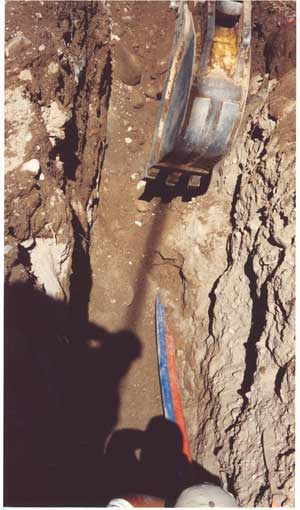
About once a day in the USA, a fiber optic cable is broken by a contractor digging around the cable, as this photo shows. Premises cables are not as vulnerable, except for damage caused by clumsy personnel or during the removal of abandoned cables. Any network is susceptible to damage so every installation needs a restoration plan.
Efficient fiber optic restoration depends on rapidly finding the problem, knowing how to fix it, having the right parts and getting the job done quickly and efficiently. Like any type of emergency, planning ahead will minimize the problems encountered.
Documentation for Restoration
Documentation is the most helpful thing you can have when trying to troubleshoot a fiber network, especially during restoration. Start with the manufacturer’s datasheets on every component you use: electronics, cables, connectors, hardware like patch panels, splice closures and even mounting hardware. Along with the data, one should have manufacturer’s “help line” contact information, which will be of immense value during restoration.
During installation, mark every fiber in every cable at every connection and keep records using cable plant documentation software or a simple spreadsheet of where every fiber goes. When tested, add loss data taken with an optical loss test set (OLTS) and optical time domain reflectometer (OTDR) data when available. Someone must be in charge of this data, including keeping it up to date if anything changes.
Equipment For Restoration
Testing and Troubleshooting
You must have available proper test equipment to troubleshoot and restore a cable plant. An OLTS should also have a power meter to test the power of the signals to determine if the problem is in the electronics or cable plant. Total failure of all fibers in the cable plant means a break or cut in the cable. For premises cables, finding the location is often simple if you have a visual fault locator or VFL, which is a bright red laser coupled into the optical fiber that allows testing continuity, tracing fibers or finding bad connectors at patch panels.
For longer cables, an OTDR will be useful. Outside plant networks should use the OTDR to document the cable plant during installation, so during restoration a simple comparison of installation data with current traces will usually find problems. OTDRs can also find non-catastrophic problems, for example when a cable is kinked or stressed, so it only has higher loss, which can also cause network problems.
Tools and Components
Once you find the problem, you have to repair it. Repair requires having the right tools, supplies and trained personnel available. Besides the test equipment needed for troubleshooting, you need tools for splicing and termination, which may include a fusion splicer for outside plant cables. You also need components necessary for restoring the cable plant.
For every installation, a reasonable amount of excess cable and installation hardware should be set aside in storage for restoration. Some users store the restoration supplies along with documentation in a sealed container ready for use. Remember that the fiber optic patchcords that connect the electronics to the cable plant can be damaged also, but are not considered repairable. Just keep replacements available.
One big problem in restoring damaged cables is pulling the two cable ends close enough to allow splicing them together. You need several meters of cable on each end to strip the cable, splice the fibers and place them in a splice closure. Designing the cable plant with local service loops is recommended. If the cable ends are too short , or the damaged cable is underground or buried, you will have to splice in a new section of cable. Since the restoration cable must match the damaged cable or at least have a greater nuber of fibers, the best source of cable for restoration is cable leftover from the original installation. Manufacturers also can supply cable restoration kits that include cable and splice closures.
What else besides cables and cable plant hardware should be in a restoration kit? You should have a termination or mechanical splice kit and proper supplies. For splices, you need splice closures with adequate space for a number of splices equal to the fiber count in the cable. All these should be placed in a clearly marked box with a copy of the cable plant documentation and stored in a safe place where those who will eventually need it can find it fast.
Preparing Personnel
Personnel must be properly trained to use this equipment and do the troubleshooting and restoration. And, of course, they must be available on a moments notice. The biggest delay in restoring a fiber optic communications link is often the chaos that ensues while personnel figure out what to do. Having a plan that is known to the responsible personnel is the most important issue.
Major users of fiber optics have restoration plans in place, personnel trained and kits of supplies ready for use. It’s doubtful that most premises users are ready for such contingencies. Users may find that the cost of owning all this expensive equipment is not economic. It may be preferable to keep an inexpensive test set consisting of a VFL and OLTS at each end of the link and having an experienced contractor on call for restoration.
Managing A Fiber Optic Project
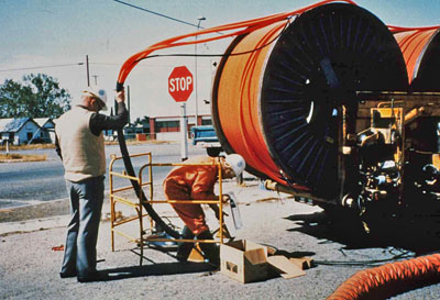
Managing a fiber optic project can be easiest part of the installation if the design and planning have been done thoroughly and completely, or, if not, the hardest. But even assuming everything has been done right, things will still probably go wrong, so planning for the unexpected is also very important. Here are some guidelines for managing the project that can minimize the problems and help in their speedy solution.
On Site Management and Supervision
First, someone has to be in charge, and everyone involved must know they are the boss, including them. During the project, they must be readily available for consultation and updates. While this may sound obvious, sometimes the network user’s representative has other responsibilities (like managing an IT department) and may not be able or willing to direct full attention to the project. Whoever is assigned the task of managing the project must be involved and available, preferably on the job site, full time. If necessary, delegate responsibility to the contracting construction supervisor with requirements for daily reports and personal updates.
Make certain that everyone responsible for parts of the project have appropriate documentation and have reviewed the installation plan. Everyone should have toured the relevant job sites and be familiar with locations. They must also know who to contact about questions on the sites, within the network user, the contractor and any outside organizations such as local governments or utilities. Everyone needs to have contact information for each other (cell phones usually, since email may be too slow and instant messaging will probably not be available to field workers.) The onsite supervisor should have a digital camera and take plenty of photos of the installation to be filed with the documentation for future reference and restoration.
Locations of components, tools and supplies should be known to all personnel. On larger jobs, managing equipment and materials may be a full time job. Special equipment, like splicing trailers or bucket trucks, should be scheduled as needed. Rental equipment should be double checked with the suppliers to ensure delivery to the job site on time. Contacts for vendor technical support should be noted on documentation for the inevitable questions arising during installation.
Contacts with Local Authorities
Outside plant installs may require local authorities to provide personnel for supervision or police for protection or traffic management on public job sites, so they must also become involved in the scheduling. If job inspections are required, arrangements should be made so that the job interruptions for inspections are minimized. Supervisory personnel must be responsible for job site safety and have appropriate contact information, including for public services like police, fire and ambulance.
If the project is large enough to last several days or more, daily meetings to review the day’s progress are advisable. At a minimum, it should involve the onsite construction supervisor and the network user’s person in charge of the project. As long as things are going well, such a meeting should be short. On longer projects, overnight security personnel at job sites should have contact information for the job manager who must be available 24/7 as well as public service contacts.
Continuous Inspection, Testing and Corrections
Inspection and testing of the installed cable plant should not be left until after the job is completed. Testing continually during installation can find and fix problems such as cable stresses or high termination losses before those problems become widespread. Each installer doing testing should have documentation with loss budget calculations and acceptable losses to use for evaluating the test results. Installers should be double-checking each other’s work to ensure quality.
What do you do when (not if) things go wrong? Here judgment calls are important. When something happens, obviously it is the responsibility of the onsite supervisor to decide quickly if they can take care of it. If not, they must know who needs to be brought in and who needs to be notified. By reviewing progress regularly, disruptions can be minimized. Equipment failures, e.g. a fusion splicer, can slow progress, but other parts of the project like cable laying can continue, with splicing resumed as soon as replacement equipment is available. Problems with termination should be reviewed by an installer with lots of experience and the cure may require new supplies or turning termination over to more experienced personnel. Never hesitate to call vendor support when these kinds of questions or problems arise.
Following the completion of the install, all relevant personnel should meet, review the project results, update the documentation and decide if anything else needs to be done before closing the project.
References and Training
References for the fiber optic designer’s bookshelf include the FOA texts,The FOA Online Reference Guide to Fiber Optics , The FOA Reference Guide to Outside Plant Fiber Optics, The FOA Reference Guide to Fiber Optics, The FOA Reference Guide to Premises Cabling, and the FOA Tech Bulletins or NECA/FOA-301 installation standard. When it comes to the NEC, Limited Energy Systems, a textbook published by the NFPA, is very useful. There are dozens of books on communications system design, but unfortunately, the fast pace of development in communications technologies means that many textbooks are hopelessly out of date unless it’s updated frequently. Better to rely on the web, especially the FOA Reference site and websites of well-established manufacturers, if you ignore the obvious hype in most white papers. (Hype is becoming so blatant and obvious that avoiding it is getting easier!)
Getting trained specifically in fiber optic network design is available through some FOA-Approved schools. The material is covered in part in some advanced fiber optic courses offered by the FOA-approved schools and by large manufacturers who help you understand how to build networks using their products. The FOA has a new FOA design certification (CFOS/D.)
Outside Plant Fiber Optic Network Design
Jump To:
The Communications System
Cabling Design
Choosing Transmission Equipment
Planning The Route
Choosing Components
Cable Plant Link Loss Budget Analysis
Project Documentation
Planning for the Installation
Planning for Restoration
Managing A Fiber Optic Project
Fiber optic network design refers to the specialized processes leading to a successful installation and operation of a fiber optic network. It includes determining the type of communication system(s) which will be carried over the network, the geographic layout (premises, campus, outside plant (OSP, etc.), the transmission equipment required and the fiber network over which it will operate. Designing a fiber optic network usually also requires interfacing to other networks which may be connected over copper cabling and wireless.
Next to consider are requirements for permits, easements, permissions and inspections. Once we get to that stage, we can consider actual component selection, placement, installation practices, testing, troubleshooting and network equipment installation and startup. Finally, we have to consider documentation, maintenance and planning for restoration in event of a future outage.
The design of the network must precede not only the installation itself, but it must be completed to estimate the cost of the project and, for the contractor, bid on the job. Design not only affects the technical aspects of the installation, but the business aspects also.
Campus network designWorking With Others
Designing a network requires working with other personnel involved in the project, even beyond the customer. These may include network engineers usually from IT (information technology) departments, architects and engineers overseeing a major project and contractors involved with building the projects. Other groups like engineers or designers involved in aspects of project design such as security, CATV or industrial system designers or specialized designers for premises cabling may also be overseeing various parts of a project that involves the design and installation of fiber optic cable plants and systems. Even company non-technical management may become involved when parts of the system are desired to be on exhibit to visitors.
Qualifications For Fiber Optic Network Designers
It’s the job of the designer to understand not only the technology of communications cabling, but also the technology of communications, and to keep abreast of the latest developments in not only the technology but the applications of both.
Designers should have an in-depth knowledge of fiber optic components and systems and installation processes as well as all applicable standards, codes and any other local regulations. They must also be familiar with most telecom technology (cabled or wireless), site surveys, local politics, codes and standards, and where to find experts in those fields when help is needed. Obviously, the fiber optic network designer must be familiar with electrical power systems, since the electronic hardware must be provided with high quality uninterruptible power at every location. And if they work for a contractor, estimating will be a very important issue, as that is where a profit or loss can be determined!
Those involved in fiber optic project design should already have a background in fiber optics, such as having completed a FOA CFOT certification course, and may have other training in the specialties of cable plant design and/or electrical contracting. It’s also very important to know how to find in-depth information, mostly on the web, about products, standards, codes and, for the OSP networks, how to use online mapping services like Google Maps. Experience with CAD systems is a definite plus.
Copper, Fiber or Wireless?
While discussions of which is better – copper, fiber or wireless – has enlivened cabling discussions for decades, it’s becoming moot. Communications technology and the end user market, it seems, have already made decisions that generally dictate the media and many networks combine all three. The designer of cabling networks, especially fiber optic networks, and their customers today generally have a pretty easy task deciding which media to use once the communications systems are chosen.
The Communications System
Before one can begin to design a fiber optic cable plant, one needs to establish with the end user or network owner where the network will be built and what communications signals it will carry. The contractor should be familiar with premises networks, where computer networks (LANs or local area networks) and security systems use structured cabling systems built around well-defined industry standards. Once the cabling exits a building, even for short links for example in a campus or metropolitan network, requirements for fiber and cable types change. Long distance links for telecommunications, CATV or utility networks have other, more stringent requirements, necessary to support longer high speed links, that must be considered.
But while the contractor generally considers the cabling requirements first, the real design starts with the communications system requirements established by the end user. One must first look at the types of equipment required for the communications systems, the speed of the network and the distances to be covered before considering anything related to the cable plant. The communications equipment will determine if fiber is necessary or preferable and what type of fiber is required.
Outside Plant Networks
Telephone networks are mainly outside plant (OSP) systems, connecting buildings over distances as short as a few hundred meters to hundreds or thousands of kilometers. Data rates for telecom are typically 2.5 to 10 gigabits per second using very high power lasers that operate exclusively over singlemode fibers. The big push for telecom is now taking fiber directly to a commercial building or the home, since the signals are now too fast for traditional twisted copper pairs.
CATV also uses singlemode fibers with systems that are either hybrid fiber-coax (HFC) or digital where the backbone is fiber and the connection to the home is on coax. Coax still works for CATV since it has very high bandwidth itself. Some CATV providers have discussed or even tried some fiber to the home, but have not seen the economics become attractive yet.
Besides telecom and CATV, there are many other OSP applications of fiber. Intelligent highways are dotted with security cameras and signs and/or signals connected on fiber. Security monitoring systems in large buildings like airports, government and commercial buildings, casinos, etc. are generally connected on fiber due to the long distances involved. Like other networks, premises applications are usually multimode while OSP is singlemode to support longer links.
Metropolitan networks owned and operated by cities can carry a variety of traffic, including surveillance cameras, emergency services, educational systems, telephone, LAN, security, traffic monitoring and control and sometimes even traffic for commercial interests using leased bandwidth on dark fibers or city-owned fibers. However, since most are designed to support longer links than premises or campus applications, singlemode is the fiber of choice.
For all except premises applications, fiber is the communications medium of choice, since its greater distance and bandwidth capabilities make it either the only choice or considerably less expensive than copper or wireless. Only inside buildings is there a choice to be made, and that choice is affected by economics, network architecture and the tradition of using copper inside buildings. Next, we’ll look at the fiber/copper/wireless choices in more detail.
Premises Networks
Premises cable systems are designed to carry computer networks based on Ethernet which currently may operate at speeds from 10 megabits per second to 10 gigabits per second. Other systems may carry security systems with digital or analog video, perimeter alarms or entry systems, which are usually low speeds, at least as far as fiber is concerned. Premises telephone systems can be carried on traditional twisted pair cables or, as is becoming more common, utilize LAN cabling with voice over IP (VoIP) technology.
Premises networks are usually short, often less than the 100 meters (about 330 feet) used as the limit for standardized structured cabling systems that allow twisted pair copper or fiber optic cabling, with backbones on campus networks used in industrial complexes or institutions as long as 500 m or more, requiring optical fiber.
Premises networks generally operate over multimode fiber. Multimode systems are less expensive than singlemode systems, not because the fiber is cheaper (it isn’t) nor because cable is cheaper (the same), but because the large core of multimode fiber allows the use of cheaper LED or VCSEL sources in transmitters, making the electronics much cheaper. Astute designers and end users often include both multimode and singlemode fibers in their backbone cables (called hybrid cables) since singlemode fibers are very inexpensive and it provides a virtually unlimited ability to expand the systems.
Premises networks will include a entrance facility where outside plant and premises communications systems meet. This facility must include not only cabling connections but compatible communications equipment. Since it is indoors, it must consider issues for building and electrical codes, such as the common requirement that bare OSP cables can only come 50 feet (about 15 meters) before being terminated in fire-rated cables unless it is in conduit.
Cabling Design
Long Distance and Outside Plant Cabling
Other than telco systems that still use copper for the final connection to the home, practically every cable in the telephone system is fiber optic. CATV companies use a high performance coax into the home, but it connects to a fiber optic backbone. The Internet backbone is all fiber. Most commercial buildings in populous areas have direct fiber connections from communications suppliers. Cities use SM fiber to connect municipal buildings, surveillance cameras, traffic signals and sometimes offer commercial and residential connections, all over singlemode fiber. Even cellular antenna towers along highways and on tall buildings usually have fiber connections. Remote areas such as central Africa depend on satellite communications since cables are too expensive to run long distances for the small amounts of traffic involved.
Designing long distance or outside plant applications generally means choosing cabling containing singlemode (SM) fiber over all other media. Most of these systems are designed to be used over distances and speeds that preclude anything but SM fiber. Occasionally other options may be more cost effective, for example if a company has two buildings on opposite sides of a highway, a line-of-sight or radio optical wireless network may be easier to use since they have lower cost of installation and are easier to obtain relevant permits.
The choice of the actual singlemode fiber, however, can depend on the application. Depending on the length of the link, the wavelength of the transmitters, data rate of the transmission and if CWDM or DWDM are planned, different types of fiber may be optimal. Refer to Chapter 5 on fiber for more details.
Premises Cabling
The desire for mobility, along with the expansion of connected services, appears to lead to a new type of corporate network. Fiber optic backbone with copper to the desktop where people want direct connections and multiple wireless access points, more than is common in the past, for full coverage and maintaining a reasonable number of users per access point is the new norm for corporate networks.
Most building management systems use proprietary copper cabling, for example thermostat wiring and paging/audio speaker systems. Security monitoring and entry systems, certainly the lower cost ones, still depend on coax copper cable, although high security facilities like government and military installations often pay the additional cost for fiber’s more secure nature.
Surveillance systems are becoming more prevalent in buildings, especially governmental, banking, or other buildings that are considered possible security risks. While coax connections are common in short links and structured cabling advocates say you can run cameras limited distances on Cat 5E or Cat 6 UPT like computer networks, fiber has become a much more common choice. Besides offering greater flexibility in camera placement because of its distance capability, fiber optic cabling is much smaller and lightweight, allowing easier installation, especially in older facilities like airports or large buildings that may have available spaces already filled with many generations of copper cabling.
When these premises communications systems connect to the outside world, it is generally to singlemode optical fiber. The entrance facility and equipment room must accommodate the equipment needed to make those connections.
Use of Cabling Standards
Many documents relating to cable plant design focus on industry standards for both communications systems and cable plants. US standards come from the TIA or Telcordia while worldwide standards may come from ISO/IEC or ITU.
It is important to realize why and by whom these standards are written. These standards are written by manufacturers of products to ensure that various manufacturers’ products work together properly. Whenever users specify standards for any project, it is important that the contractor/installer understand what standards are being referenced and ensure that such standards are relevant to the job being done.
Choosing Transmission Equipment
Choosing
transmission equipment is the next step in designing a fiber optic
network. This step will usually be a cooperative venture involving the
customer, who knows what kinds of data they need to communicate, the
designer and installer, and the manufacturers of transmission
equipment. Transmission equipment and the cable plant are tightly
interrelated. The distance and bandwidth will help determine the fiber
type necessary and that will dictate the optical interfaces on the
cable plant. The ease of choosing equipment may depend on the type of
communications equipment needed.Telecom has been standardized on fiber optics for 30 years now, so they have plenty of experience building and installing equipment. Since most telecom equipment uses industry conventions, you can usually find equipment for telecom transmission that will be available for short links (usually metropolitan networks, maybe up to 20-30 km), long distance and then really long distance like undersea runs. All run on singlemode fiber, but may specify different types of singlemode.
Shorter telecom links will use 1310 nm lasers on regular singlemode fiber, often referred to as G.652 fiber, it’s international standard. Longer links will use a dispersion-shifted fiber optimized for operation with 1550 nm lasers (G.652 fiber). For most applications, one of these will be used. Most telco equipment companies offer both options.
Most CATV links are AM (analog) systems based on special linear lasers called distributed feedback (DFB) lasers using either 1310 nm or 1550 nm operating on regular singlemode fibers. As CATV moves to digital transmission, it will use technology more like telecom, which is already all digital.
The choices become more complex when it comes to data and CCTV because the applications are so varied and standards may not exist. In addition, equipment may not be available with fiber optic transmission options, requiring conversion from copper ports to fiber using devices called media converters.
In computer networks, the Ethernet standards, created by the IEEE 802.3 committee, are fully standardized. You can read the standards and see how far each equipment option can transmit over different types of fiber, choosing the one that meets your needs. Most network hardware like switches or routers are available with optional fiber optic interfaces, but PCs generally only come with UTP copper interfaces that require media converters. An Internet search for “fiber optic media converters” will provide you with dozens of sources of these inexpensive devices. Media converters will also allow the choice of media appropriate for the customer application, allowing use with multimode or singlemode fiber and may even offer transceiver options for the distance that must be covered by the link.
CCTV is a similar application. More cameras now come with fiber interfaces since so many CCTV systems are in locations like big buildings, airports, or areas where the distances exceed the capability of coax transmission. If not, video media converters, usually available from the same vendors as the Ethernet media converters, are readily available and also inexpensive. Again, choose converters that meet the link requirements set by the customer application, which in the case of video, not only includes distance but also functions, as some video links carry control signals to the camera for camera pan, zoom and tilt in addition to video back to a central location.
What about industrial data links? Many factories use fiber optics for its immunity to electromagnetic interference. But industrial links may use proprietary means to send data converted from old copper standards like RS-232, the ancient serial interface once available on every PC, SCADA popular in the utility industry, or even simple relay closures. Many companies that build these control links offer fiber optic interfaces themselves in response to customer requests. Some of these links have been available for decades, as industrial applications were some of the first premises uses of fiber optics, dating back to before 1980.
Whatever the application, it’s important for the end user and the cabling contractor to discuss the actual application with the manufacturer of the transmission hardware to ensure getting the proper equipment. While the telecom and CATV applications are cut and dried and the data (Ethernet) applications covered by standards, it is our experience that not all manufacturers specify their products in exactly the same way.
One company in the industrial marketplace offered about fifteen different fiber optic products, mainly media converters for their control equipment. However, those fifteen products had been designed by at least a dozen different engineers, not all of whom were familiar with fiber optics and especially fiber jargon and specifications. As a result, one could not compare the products to make a choice or design them into a network based on specifications. Until their design, sales and applications engineers were trained in fiber optics and created guidelines for product applications, they suffered from continual problems in customer application.
The only way to make sure you are choosing the proper transmission equipment is to make absolutely certain the customer and equipment vendor – and you – are communicating clearly what you are planning to do.
Planning The Route
Having decided to use fiber optics and chosen equipment appropriate for the application, it’s time to determine exactly where the cable plant and hardware will be located. One thing to remember – every installation will be unique. The actual placement of the cable plant will be determined by the physical locations along the route, local building codes or laws and other individuals involved in the designs. As usual, premises and outside plant installations are different so we will consider them separately.
Premises and campus installations can be simpler since the physical area involved is smaller and the options fewer. Start with a good set of architectural drawings and, if possible, contact the architect, contractor and/or building manager. Having access to them means you have someone to ask for information and advice. Hopefully the drawings are available as CAD files so you can have a copy to do the network cabling design in your computer, which makes tweaking and documenting the design so much easier.
If the building is still in the design stage, you may have the opportunity to provide inputs on the needs of the cable plant. Ideally, that means you can influence the location of equipment rooms, routing of cable trays and conduits, availability of adequate conditioned power and separate data grounds, sufficient air-conditioning and other needs of the network. For pre-existing buildings, detailed architectural drawings will provide you with the ability to route cabling and network equipment around the obstacles invariably in your way.
Outside plant (OSP) cabling installations have enormous variety depending on the route the cable must take. The route may cross long lengths of open fields, run along paved rural or urban roads, cross roads, ravines, rivers or lakes, or, more likely, some combination of all of these. It could require buried cables, aerial cables or underwater cables. Cable may be in conduit, innerduct or direct buried, aerial cables may be self-supporting or lashed to a messenger. Longer runs often include crossing water, so the cable may be underwater or be lashed across a bridge with other cables.
Site Visits
And as soon as possible, you must visit the site or route where the network will be installed. Outside plant routes need to be driven or walked every foot of the way to determine the best options for cable placement, obstacles to be avoided or overcome, and to determine what local entities may have input into the routing. Often cities or other governments will know of available conduits or rules on using utility poles that can save design time and effort.
For installations inside current buildings, you should inspect every area to be absolutely certain you know what the building really looks like and then mark up drawings to reflect reality, especially all obstacles to running cabling and hardware and walls requiring firestopping that are not on the current drawings. Take pictures if you can. For buildings under construction, a site visit is still a good idea, just to get a feeling of what the final structure will be like and to get to know the construction managers you will be working with. They may be the best source of information on who the local authorities are who will be inspecting your work and what they expect.
OSP network route on satellite mapWith
all those options on OSP installations, where do you start? With a good
map. Not just a road map or a topographical map, but satellite images
overlaid on roads is much better, like “Google Maps” can provide.
Creating a route map is the first step, noting other utilities along
the route on that map, and checking with groups that document the
current utilities to prevent contractors from damaging currently
installed pipes and cables. Once you have marked up maps, the real “fun” begins: finding out whose permission you need to run your cabling. OSP installs are subject to approval by local, state and federal authorities who will influence heavily how your project is designed. Some cities, for example, ban aerial cables. Some have already buried conduit which you can use for specific routes. Since many municipalities have installed city-owned fiber networks, they may have fiber you can rent, rather than go through the hassle of installing your own.
Unless you are doing work for a utility that has someone who already has the contacts and hopefully easements needed, you may get to know a whole new set of people who have control over your activities. And you have to plan for adequate time to get approval from everyone who is involved.
Call Before You Dig
Digging safely is vitally important. The risk is not just interrupting communications, but the life-threatening risk of digging up high voltage or gas lines. Some obstacles may be found during site visits, where signs like these are visible. There are several services that maintain databases of the location of underground services that must be contacted before any digging occurs, but mapping these should be done during the design phase and double-checked before digging to ensure having the latest data.
If all this sounds vague, it is. Every project is different and requires some careful analysis of the conditions before even beginning to choose fiber optic components and plan the actual installation. Experience is the best teacher.
Choosing Components
Choosing Components For Outside Plant Installations
The choice of outside plant fiber optic (OSP) components begins with developing the route the cable plant will follow. Once the route is set, one knows where cables will be run, where splices are located and where the cables will be terminated. All that determines what choices must be made on cable type, hardware and sometimes installation methodology.
Cables
When choosing components, most projects start with the choice of a cable. Cable designs are optimized for the application type. In OSP installations, cables may be underground, direct buried, aerial or submarine (or simply underwater.)
Underground cables are generally installed in conduit which is usually a 4 inch (10 cm) conduit with several innerducts for pulling cables. Here cables are designed for high pulling tension and lubricants are used to reduce friction on longer pulls. Automated pulling equipment that limits pulling tension protects the cables. Very long runs or those with more bends in the conduit may need intermediate pulls where cable is pulled, figure-8ed and then pulled to the next stage or intermediate pulling equipment is used. Splices on underground cables are generally stored above ground in a pedestal or in a vault underground. Sufficient excess cable is needed to allow splicing in a controlled environment, usually a splicing trailer, and the storage of excess cable must be considered in the planning stage.
Direct buried cable is placed underground without conduit. Here the cable must be designed to withstand the rigors of being buried in dirt, so it is generally a more rugged cable, armored to prevent harm from rodent chewing or the pressures of dirt and rocks in which it is buried. Direct burial is generally limited to areas where the ground is mostly soil with few rocks down to the depth required so trenching or plowing in cable is easily accomplished. Splices on direct buried cables can be stored above ground in a pedestal or buried underground. Sufficient excess cable is needed to allow splicing in a controlled environment, usually a splicing trailer, and the storage of excess cable must be considered.
Aerial installations go from pole to pole, but the method of securing cables can vary depending on the situation. Some cables are lashed to messengers or other cables, such as CATV where light fiber cables are often lashed to the heavy coax already in place. Cables are available in a “8” configuration with an attached steel messenger that provides the strength to withstand tension on the cable. Some cables are made to directly be supported without a messenger, called all-dielectric sefl-supporting cables that use special hardware on poles to hold the cables. Optical ground wire is used by utilities for high voltage distribution lines. This cable is an electrical cable with fibers in the middle in a hermetically-sealed metal tube. It is installed just like standard electrical conductors. Splices on aerial cables can be supported on the cables or placed on poles or towers, Most splices are done on the ground, although it is sometimes done in a bucket or even on a tent supported on the pole or tower. Hardware is available for coiling and storing excess cable.
Sometime OSP installations involve running cables across rivers or lakes where other routes are not possible. Special cables are available for this that are more rugged and sealed. Even underwater splice hardware is available. Landings on the shore need to be planned to prevent damage, generally by burying the cable close to shore and marking the landing. Transoceanic links are similar but much more complex, requiring special ships designed for cable laying.
Since OSP applications often use significant lengths of cables, the cables can be made to order, allowing optimization for that particular installation. This usually allows saving costs but requires more knowledge on the part of the user and more time to negotiate with several cable manufacturers.
To begin specifying the cable, one must know how many fibers of what type will be included in each cable. It’s important to realize that fiber, especially singlemode fiber used in virtually all OSP installations, is cheap and installation is expensive. Installation of an OSP cable may cost a hundred times the cost of the cable itself. Choosing a singlemode fiber is easy, with basic 1300 nm singlemode (called G.652 fiber) adequate for all but the longest links or those using wavelength-division multiplexing. Those may need special fiber optimized at 1500-1600 nm (G.653 or G.654). For premises and campus cable plants, OM3 type laser-optimized 50/125 multimode fiber is probably the best choice for any multimode OSP runs, as its lower attenuation and higher bandwidth will make most networks work better.
Including more fibers in a cable will not increase the cable cost proportionally; the basic cost of making a cable is fixed but adding fibers will not increase the cost much at all. Choosing a standard design will help reduce costs too, as manufacturers may have the cable in stock or be able to make your cable at the same time as others of similar design. The only real cost for adding more fibers is additional splicing and termination costs, still small with respect to total installed cost. And remember that having additional fibers for future expansion, backup systems or in case of breaks involving individual fibers can save many future headaches.
Common traits of all outside plant cables include strength and water or moisture protection. The necessary strength of the cable will depend on the installation method (see below.) All cables installed outdoors must be rated for moisture and water resistance. Until recently, most people chose a gel-filled cable, but now dry-water blocked cables are widely available and preferred by many users. These cables use water-absorbing tape and power that expands and seals the cable if any water enters the cable. Installers especially prefer the dry cables as it does not require the messy, tedious removal of the gel used in many cables, greatly reducing cable preparation for splicing or termination.
OSP cable construction types are specifically designed for strength depending on where they are to be direct buried, buried in conduit, placed underwater or run aerially on poles. The proper type must be chosen for the cable runs. Some applications may even use several types of cable. Having good construction plans will help in working with cable manufacturers to find the appropriate cable types and ordering sufficient quantities. One must always order more cable than route lengths, to allow for service loops, preparation for termination and excess to save for possible restoration needs in the future.
Like cable types, cable plant hardware types are quite diverse and should be chosen to match the application type and cable types being used. With so many choices in hardware, working with cable manufacturers is the most expeditious way to chose hardware and ensure compatibility. Besides cable compatibility, the hardware must be appropriate for the location, which can be outdoors, hung on poles, buried, underwater, inside pedestals, vaults or buildings, etc. Sometimes the hardware will need to be compatible with local zoning, for example in subdivisions or business parks. The time consumed in choosing this hardware can be lengthy, but is very important for the long term reliability of the cable plant.
Splicing And Termination Hardware
Splicing and termination are the final category of components to be chosen. Most OSP singlemode fiber is fusion spliced for low loss, low reflectance and reliability. Multimode fiber, especially OM2, 3 and 4, is also easily fusion spliced, but if only a few splices are necessary, mechanical splicing may provide adequate performance and reliability.
Finished splices are placed in a splice tray and placed in a splice closure outdoors or optionally in trays on patch panels indoors. They are sealed to prevent moisture reaching the splices and are designed to be re-entered for repair or re-routing fibers. Splice closures are available in hundreds of designs, depending on the placement of the closure, for example underground in a manhole or vault, above ground in a pedestal, buried underground or mounted on a pole. Closures must also be chosen by the number and types of cables being spliced and whether they enter at both ends or only one. The numbers of cables and splices that a closure can accommodate will determine the size of the closure, and those for high fiber count cables can get quite large.
Splice trays generally hold twelve single fiber fusion splices but may hold fewer ribbon or mechanical splices. Each splice tray should securely hold the splice and have a cover to protect the fibers when stacked in the closure.
Singlemode fibers are best terminated by fusion spicing factory-made pigtails onto fibers in the cable and protecting the splices in a closure or patch panel tray. If termination is done directly on multimode OSP cables, breakout kits will be necessary to sleeve fibers for reliability when connectors are directly attached. This takes more installation time than splicing pre-terminated pigtails on the cables, as is common with singlemode fiber cables, and may not save any costs. Even complete preterminated outside cable plant systems are becoming available, reducing the time necessary for termination and splicing. Talk to the cable manufacturers to determine feasibility of this option.
Outdoor terminations are sometimes housed in pedestals or equipment housings such as those used for local phone switches or traffic control systems. Some of these closures may not be fully sealed from dust and moisture, in which case it is recommended that the fiber connections be inside a more protective housing to prevent future unreliability.
Choosing the proper components for OSP installations can take time, but is important for system operation. Once components are chosen, the materials lists are added to the documentation for purchase, installation and future reference.
Choosing Components For Premises Installations
Premises cabling and outside plant cabling will coexist in the entrance facility or the equipment room where the two are connected. The choice of premises fiber optic components are affected by several factors, including the choice of communications equipment, physical routing of the cable plant and building codes and regulations. If the design is a corporate network (LAN), the design will probably include a fiber optic backbone connecting computer rooms to wiring closets. The wiring closets house switches that convert the fiber backbone to UTP copper for cable connected desktops and either copper or fiber to wireless access points. Some desktops, especially in engineering or design departments, may require fiber to the desktop for it’s greater bandwidth. Extra cables or fibers may be needed for security systems (alarms, access systems or CCTV cameras) and building management systems also.
Design of the fiber optic cable plant requires coordinating with everyone who is involved in the network in any way, including IT personnel, company management, architects and engineers, etc. to ensure all cabling requirements are considered at one time, to allow sharing resources.
As in OSP design, consider the fiber choice first. Most premises networks use multimode fiber, but many users now install hybrid cables with singlemode fibers for future expansion. The 62.5/125 micron fiber (OM1 fiber) that has been used for almost two decades has mostly been superceded by the new 50/125 laser-optimized fiber (OM3), as it offers substantial bandwidth/distance advantages.
Virtually all equipment will operate over 50/125 OM3 fiber just as well as it did on 62.5/125 OM1 fiber, but it’s always a good idea to check with the equipment manufacturers to be sure. Remember in the design documentation to include directions to mark all cables and patchpanels with aqua-colored tags, indicative of OM3 fiber.
Cable in premises applications is generally either distribution or breakout cable. Distribution cables have more fibers in a smaller diameter cable, but require termination inside patch panels or wall mounted boxes. Breakout cables are bulky, but they allow direct connection without hardware, making them convenient for industrial use. Fiber count can be an issue, as backbone cables now have many fibers for current use, future expansion and spares, making distribution cables the more popular choice. The cable jacket must be fire-retardant per the NEC, generally OFNR-rated (Riser) unless the cable in air-handling areas above ceilings, where OFNP (plenum) is needed. Cable jacket color for OM3 cables can be ordered in aqua for identification as both fiber optics and OM3 50/125 fibers.
If the cable is going to be run between buildings, indoor/outdoor designs are now available that have dry water-blocking and a double jacket. The outer jacket is moisture-resistant for outdoor use but can be easily stripped, leaving the fire-rated inner jacket for indoor runs.
Fiber optic connector choices are also changing. STs and even SCs are succumbing to the success of the smaller LC connector. Since most fast (gigabit and above) equipment uses LC connectors, using them in the cable plant means only one connector needs to be supported. The LC offers another big advantage for those users who are upgrading to OM3 fiber. The LC connector is incompatible with SC and ST connectors, so using it on 50/125 fiber cable plants prevents mixing 50 and 62.5 fibers with high fiber mismatch losses.
Premises fiber optic cables need to be run separately from copper cables to prevent crushing. Sometimes they are hung carefully below copper cable trays or pulled in innerduct. Using innerduct can save installation time, since the duct (which can be purchased with pull tapes already inside) can be installed quickly without fear of damage and then the fiber optic cable pulled quickly and easily. Some applications may require installing fiber optic cables inside conduit, which requires care to minimize bends, provide intermediate pulls to limit pulling force or use fiber optic cable lubricants.
The hardware necessary for the installation will need to be chosen based on where the cables are terminated. Premises runs are generally point-to-point and are not spliced. Wherever possible, allow room for large radii in the patch panels or wall-mounted boxes to minimize stress on the fibers. Choose hardware that is easy to enter for moves, adds and changes but lockable to prevent intrusion.
In premises applications, it’s worth considering a preterminated system. These use backbone cables terminated in multifiber connectors and preterminated patch panel modules. If the facility layout is properly designed, the cable manufacturer can work with you to create a “plug and play” system that needs no on-site termination and the cost may be very competitive to a field-terminated system.
Creating A Materials List
For every installation, a complete materials list must be created listing each component needed and quantities required. This list will be used by the installation crew, but first it will be used to estimate the cost of the project.
It is very important to list every component. Some components can be estimated based on other quantities. Ducts for example will be ordered in lengths similar to the cable pulled into them. Each fiber needs termination on both ends of the cable plant. Splice trays and closures must be ordered according to the numbers of fibers in the cables.
You should include extra quantities for installation. Every splice point, for example, needs 10-20 meters extra cable for splicing in a splice trailer, stripping for the splice and service loops. Extra cable should also be ordered to be kept for possible future restoration. Extra connectors or pigtails are needed to replace those improperly installed during installation. Some contractors routinely order 2-5% more than they estimate is necessary for the job.
While ordering more components than necessary can be costly, it’s less expensive than being short during the actual installation, especially for special order items like cables or patchcords. Excess components should be packed and stored as part of a restoration kit.
Cable Plant Link Loss Budget Analysis
Loss budget analysis is the calculation and verification of a fiber optic system's operating characteristics. This encompasses items such as routing, electronics, wavelengths, fiber type, and circuit length. Attenuation and bandwidth are the key parameters for budget loss analysis. The designer should analyze link loss early in the design stage prior to installing a fiber optic system to make certain the system will work over the proposed cable plant.
Both the passive and active components of the circuit can be included in the budget loss calculation. Passive loss is made up of fiber loss, connector loss, and splice loss. Don't forget any couplers or splitters in the link. If the system electronics are already chosen, active components such as wavelength, transmitter power, receiver sensitivity, and dynamic range can be considered. If the electronics are not known, industry generic or standard loss values can be used for the loss budget. Prior to system turn up, test the insertion loss of the cable plant with a source and power meter to ensure that it is within the loss budget.
The idea of a loss budget is to insure the network equipment will work over the installed fiber optic link. It is normal to be conservative over the specifications. Don't use the best possible specs for fiber attenuation or connector loss to allow some margin for installation and component degradation over time.
The best way to illustrate calculating a loss budget is to show how it's done for a typical cable plant, here a 2 km hybrid multimode/singlemode link with 5 connections (2 connectors at each end and 3 connections at patch panels in the link) and one splice in the middle. See the drawings below of the link layout and the instantaneous power in the link at any point along it's length, scaled exactly to the link drawing above it.
Cable Plant Passive Component Loss
Step 1. Calculate fiber loss at the operating wavelengths (length times standard estimates of loss at each wavelength)
| Cable Length (km) | 2.0 | 2.0 | 2.0 | 2.0 |
| Fiber Type | Multimode | Singlemode | ||
| Wavelength (nm) | 850 | 1300 | 1300 | 1550 |
| Fiber Atten. (dB/km) | 3 [3.5] | 1 [1.5] | 0.4 [1/0.5] | 0.3 [1/0.5] |
| Total Fiber Loss (dB) | 6.0 [7.0] | 2.0 [3.0] | 0.8 [2/1 | 0.6 [2/1] |
(All specifications in brackets are maximum values per EIA/TIA 568 standard. For singlemode fiber, a higher loss is allowed for premises applications, 1 dB/km for premises, 0.5 dB/km for outside plant. )
Step 2. Connector Loss
Multimode connectors will have losses of 0.2-0.5 dB typically. Singlemode connectors, which are factory made and fusion spliced on will have losses of 0.1-0.2 dB. Field terminated singlemode connectors may have losses as high as 0.5-1.0 dB. Let's calculate it at both typical and worst case values.
| Connector Loss | 0.3 dB (typical adhesive/polish connector) | 0.75 dB (prepolished/splice connector and TIA-568 max acceptable) |
| Total # of Connectors | 5 | 5 |
| Total Connector Loss | 1.5 dB | 3.75 dB |
(All connectors are allowed 0.75 max per EIA/TIA 568 standard)
Many designers and technicians forget when doing a loss budget that the connectors on the end of the cable plant must be included in the loss budget. When the cable plant is tested, the reference cables will mate with those connectors and their loss will be included in the measurements.
Step 3. Splice Loss
Multimode splices are usually made with mechanical splices, although some fusion splicing is used. The larger core and multiple layers make fusion splicing abut the same loss as mechanical splicing, but fusion is more reliable in adverse environments. Figure 0.1-0.5 dB for multimode splices, 0.3 being a good average for an experienced installer. Fusion splicing of singlemode fiber will typically have less than 0.05 dB (that's right, less than a tenth of a dB!)
| Splice Loss | 0.3 dB |
| Total # splices | 1 |
| Total Splice Loss | 0.3 dB |
(For this loss budget calculation, all splices are allowed 0.3 max per EIA/TIA 568 standard)
Step 4. Total Cable Plant Loss
Add together the fiber, connector and splice losses to get the total link loss of the cable plant.
| Best Case [TIA 568 Max] | | Best Case [TIA 568 Max] | | |
| Wavelength (nm) | 850 | 1300 | 1300 | 1550 |
| Total Fiber Loss (dB) | 6.0 [7.0] | 2.0 [3.0] | 0.8 [2/1] | 0.6 [2/1] |
| Total Connector Loss (dB) | 1.5 [3.75] | 1.5 [3.75] | 1.5 [3.75] | 1.5 [3.75] |
| Total Splice Loss (dB) | 0.3 [0.3] | 0.3 [0.3] | 0.3 [0.3] | 0.3 [0.3] |
| Other (dB) | 0 | 0 | 0 | 0 |
| Total Link Loss (dB) | 7.8 [11.05] | 3.8 [7.05] | 2.6 [6.05/5.05] | 2.4 [6.05/5.05] |
These values of cable plant loss should be the criteria for testing. Allow +/- 0.2 -0.5 dB for measurement uncertainty and that becomes your pass/fail criterion.
Equipment Link Loss Budget Calculation
Link loss budget for network hardware depends on the dynamic range, the difference between the sensitivity of the receiver and the output of the source into the fiber. You need some margin for system degradation over time or environment, so subtract that margin (as much as 3dB) to get the loss budget for the link.
Step 5. Data From Manufacturer's Specification for Active Components (Typical 100 Mb/s multimode digital link using a 1300 nm LED source.)
| Operating Wavelength (nm) | 1300 |
| Fiber Type | MM |
| Receiver Sensitivity (dBm@ required BER) | -31 |
| Average Transmitter Output (dBm) | -16 |
| Dynamic Range (dB) | 15 |
| Recommended Excess Margin (dB) | 3 |
Step 6. Loss Margin Calculation
| Dynamic Range (dB) (above) | 15 | 15 |
| Cable Plant Link Loss (dB @ 1300 nm) | 3.8 (Typical) | 7.05 (TIA) |
| Link Loss Margin (dB) | 11.2 | 7.95 |
As a general rule, the Link Loss Margin should be greater than approximately 3 dB to allow for link degradation over time. LEDs in the transmitter may age and lose power, connectors or splices may degrade or connectors may get dirty if opened for rerouting or testing. If cables are accidentally cut, excess margin will be needed to accommodate splices for restoration.
More on link loss budgets.
Project Documentation
Documentation of the cable plant is a necessary part of the design and installation process for a fiber optic network that is often overlooked. Documenting the installation properly during the planning process will save time and material in the installation. It will speed the cable installation and testing since the routing and terminations are already known. After component installation, the documentation should be completed with loss test data for acceptance by the end user. During troubleshooting, documentation eases tracing links and finding faults. Proper documentation is usually required for customer acceptance of the installation.
The documentation process begins at the initiation of the project and continues through to the finish. It must begin with the actual cable plant path or location. OSP cables require documentation as to the overall route, but also details on exact locations, e.g. on which side of streets, which cable on poles, where and how deep buried cables and splice closures lay and if markers or tracing tape is buried with the cable. Premises cables require similar details inside a building in order for the cable to be located anywhere in the path.
Most of this data can be kept in CAD drawings and a database or commercial software that stores component, connection and test data. Long outside plant links that include splices may also have OTDR traces which should be stored as printouts and possibly in computer files archived on disks for later viewing in case of problems. A computer with proper software for viewing traces must be available, so a copy of the viewing program should be on the disks with the files. If the OTDR data is stored digitally, a listing of data files should be kept with the documentation to allow finding specific OTDR traces more easily.
The Documentation Process
Documentation begins with a basic layout for the network. A sketch on building blueprints may work for a small building but a large campus, metropolitan or long distance network will probably need a complete CAD layout. The best way to set up the data is to use a facility drawing and add the locations of all cables and connection points. Identify all the cables and racks or panels in closets and then you are ready to transfer this data to a database.
Fiber optic cables, especially backbone cables, may contain many fibers that connect a number of different links which may not all be going to the same place. The fiber optic cable plant, therefore, must be documented for cable location, the path of each fiber, interconnections and test results. You should record the specifications on every cable and fiber: the manufacturer, the type of cable and fiber, how many fibers, cable construction type, estimated length, and installation technique (buried, aerial, plenum, riser, etc.)
It will help to know what types of panels and hardware are being used, and what end equipment is to be connected. If you are installing a big cable plant with many dark (unused) fibers, some will probably be left open or unterminated at the panels, and that must be documented also. Whenever designing a network, it's a very good idea to have spare fibers and interconnection points in panels for future expansion, rerouting for repair or moving network equipment.
Documentation is more than records. All components should be labeled with color-coded permanent labels in accessible locations. Once a scheme of labeling fibers has been determined, each cable, accessible fiber and termination point requires some labeling for identification. A simple scheme is preferred and if possible, explanations provided on patch panels or inside the cover of termination boxes.
Protecting Records
Cable plant documentation records are very important documents. Keep several backup copies of each document, whether it is stored in a computer or on paper, in different locations for safekeeping. If a copy is presented to the customer, the installer should maintain their own records for future work on the project. One complete set on paper should be kept with a “restoration kit” of appropriate components, tools directions in case of outages or cable damage. Documentation should be kept up to date to be useful so that task should be assigned to one on-site person with instructions to inform all parties keeping copies of the records of updates needed. Access to modify records should be restricted to stop unauthorized changes to the documentation.
Planning for the Installation
Once the design of a fiber optic project is complete and documented, one might think the bulk of the design work is done. But in fact, it’s just beginning. The next step is to plan for the actual installation. Planning for the installation is a critical phase of any project as it involves coordinating activities of many people and companies. The best way to keep everything straight is probably to develop a checklist based on the design during the early stages of the project.
The Project Manager
Perhaps the most important issue is to have a person who is the main point of contact for the project. The project manager needs to be involved from the beginning, understands the aims of the project, the technical aspects, the physical layout, and is familiar with all the personnel and companies who will be involved. Likewise all the parties need to know this person, how to contact them (even 24/7 during the actual install) and who is the backup if one is needed.
The backup person should also be involved to such a degree that they can answer most questions, may even be more technically savvy on the project, but may not have full decision-making authority. The backup on big jobs may well be the person maintaining the documentation and schedules, keeping track of purchases and deliveries, permits, subcontractors, etc. while the project manager is more of a hands-on manager.
Design Checklist
Planning for a project is critical to the success of the project. The best way is to develop a checklist before beginning the design process. The checklist below is comprehensive but each project will have some of its own unique requirements that need to be added. Not all steps need be done serially, as some can be done in parallel to reduce time required for designing the project. The designer must interface with many other people and organizations in designing a project so contacts for outside sources should be maintained with the design documentation.
Design process
Link communications requirements
Link route chosen, inspected, special requirements noted including inspections and permits
Specify communications equipment and component requirements
Specify cable plant components
Determine coordination with facilities, electrical and other personnel
Documentation completed and ready for installation
Write test plan
Write restoration plans
Contractor package for the install
Documentation, drawings, bills of materials, instructions
Permits available for inspection
Guidelines to inspect workmanship at every step, test plan
Daily review of progress, test data
Safety rules to be posted on the job site(s) and reviewed with all supervisors and installation personnel
Requirements for completion of cable plant installation
Final inspection
Review test data on cable plant
Instructions to set up and test communications system
Final update of documentation
Update and complete restoration plan, store components and documentation
Developing A Project Checklist
The final project checklist will have many items, all of great importance. Each item needs a full description, where and when it will be needed and who is responsible for it. See Chapter 10 for a recommended project installation checklist. Components like cables and cable plant hardware should indicate vendors, delivery times and where, when and sometimes how it needs to be delivered. Special installation equipment needs to be scheduled also, with notes of what is needed to be purchased and what will be rented. If the jobsite is not secure and the install will take more than a day, security guards at the jobsite(s) may need to be arranged.
A work plan should be developed that indicates what specialties are going to be needed, where and when. Outside plant installations (OSP) often have one crew pulling cable, especially specialty installs like direct burial, aerial or underwater, another crew splicing and perhaps even another testing. OSP installers often do just part of the job since they need skills and training on specialized equipment like fusion splicers or OTDRs and installation practices like climbing poles or plowing-in cables. Inputs from the installation crews can help determine the approximate time needed for each stage of the installation and what might go wrong that can affect the schedule.
And things will go wrong. All personnel working on the project should be briefed on the safety rules and preferably be given a written copy. Supervisors and workers should have contact numbers for the project manager, backup and all other personnel they may need to contact. Since some projects require working outside normal work hours, for example airports or busy government buildings where cabling is often done overnight, having a project manager available – preferably onsite – while the work is being done is very important.
During the installation itself, a knowledgeable person should be onsite to monitor the progress of installation, inspect workmanship, review test data, create daily progress reports and immediately notify the proper management if something looks awry. If the project manager is not technically qualified, having someone available who is technical is important. That person should have the authority to stop work or require fixes if major problems are found.
Facilities and Power/Ground issues
This chapter primarily focuses on the unique aspects of fiber optic cable plant design and installation, but this process cannot be done in a vacuum. Cable plants may require municipal permits, cooperation from other organizations to allow access through their property and construction disruptions. Any communications system requires not only the cable plant but facilities for termination at each end, placing communications equipment, providing power (usually uninterruptible data quality power) and a separate data ground. Inside the facility, connections must be made to the end users of the link.
The large number of options involved in almost every project make it impossible to summarize the issues in a few sentences, so let’s just say you must consider the final, complete design to gain cooperation and coordinate the final installation. One of the most valuable assets you can have when designing and installing a fiber optic project is an experienced contractor. Developing A Test Plan
Every installation requires confirmation that components are installed properly. The installer or contractor wants to ensure the work is done properly so the customer is satisfied and callbacks for repair will not be necessary. Customers generally require test results as well as a final visual inspection as part of the documentation of a proper installation before approving payment.
In our experience, however, there is often confusion about exactly what should be tested and how documentation of test results is to be done on fiber optic projects. These issues should be agreed upon during the design phase of the project. Project paperwork should include specifications for testing, references to industry standards and acceptable test results based on a loss budget analysis done during the design phase of the project.
The process of testing any fiber optic cable plant may require testing three times, testing cable on the reel before installation, testing each segment as it is installed, including verifying every splice as it is made using an OTDR and finally testing complete end to end loss of every fiber in the cable plant. Practical testing usually means testing only a few fibers on each cable reel for continuity before installation to ensure there has been no damage to the cable during shipment. Then each segment is tested as it is spliced and/or terminated by the installers. Finally the entire cable run is plugged together and tested for end-to-end loss for final documentation.
One should require visual inspection of cable reels upon acceptance and, if visible damage is detected, testing the cable on the reel for continuity before installing it, to ensure no damage was done in shipment from the manufacturer to the job site. Since the cost of installation usually is high, often much higher than the cost of materials, it only makes sense to ensure that one does not install bad cable, which would then have to be removed and replaced. It is generally sufficient to just test continuity with a fiber tracer or visual fault locator. However, long spools of cable may be tested with an OTDR if damage is suspected and one wants to document the damage or determine if some of the cable needs to be cut off and discarded (or retained to get credit for the damaged materials.)
After cable installation, splicing and termination, each segment of the cable plant should be tested individually as it is installed, to ensure each splice, connector and cable is good. One should never complete splicing cables without verifying the splices are properly done with an OTDR before sealing the splice closure. Finally each end to end run (from equipment to equipment connected on the cable plant) should be tested for loss as required by all standards. Remember that each fiber in each cable will need to be tested, so the total number of tests to be performed is calculated from the number of cable segments times the number of fibers in each cable. This can be a time-consuming process.
Required vs. Optional Testing
Testing the complete cable plant requires insertion loss testing with a source and power meter or optical loss test set (OLTS) per TIA standard test procedure OFSTP-14 for multimode or OFSTP-7 for singlemode. The test plan should specify the “0 dB” reference method option (one, two or three reference cables) as this will affect the value of the loss. TIA 568 calls for a one cable reference, but this may not be possible with all combinations of test sets and cable plant connectors. The required test methods need to be agreed upon by the contractor and user beforehand.
OTDR testing is generally done on outside plant cables, but OTDR testing alone is not acceptable for cable plant certification. Long lengths of outside plant cabling which include splices should be tested with an OTDR to verify splice performance and look for problems caused by stress on the cable during installation.
While there are advocates of using OTDRs to test any cable plant installation, including short premises cables, it is not required by industry standards nor is it recommended for premises cabling. The shorter lengths of premises cabling runs and frequent connections with high reflectance often create confusing OTDR traces that cause problems for the OTDR autotest function and are sometimes difficult for even experienced OTDR users to interpret properly.
Coordinating Testing and Documentation
The Test Plan should be coordinated with the cable plant documentation. The documentation must show what links need testing and what test results are expected based on loss budget calculations. The Test Plan should also specify how the test data are incorporated into the documentation for acceptance of the installation and for reference in case of future cabling problems that require emergency restoration.
Planning for Restoration
About once a day in the USA, a fiber optic cable is broken by a contractor digging around the cable, as this photo shows. Premises cables are not as vulnerable, except for damage caused by clumsy personnel or during the removal of abandoned cables. Any network is susceptible to damage so every installation needs a restoration plan.
Efficient fiber optic restoration depends on rapidly finding the problem, knowing how to fix it, having the right parts and getting the job done quickly and efficiently. Like any type of emergency, planning ahead will minimize the problems encountered.
Documentation for Restoration
Documentation is the most helpful thing you can have when trying to troubleshoot a fiber network, especially during restoration. Start with the manufacturer’s datasheets on every component you use: electronics, cables, connectors, hardware like patch panels, splice closures and even mounting hardware. Along with the data, one should have manufacturer’s “help line” contact information, which will be of immense value during restoration.
During installation, mark every fiber in every cable at every connection and keep records using cable plant documentation software or a simple spreadsheet of where every fiber goes. When tested, add loss data taken with an optical loss test set (OLTS) and optical time domain reflectometer (OTDR) data when available. Someone must be in charge of this data, including keeping it up to date if anything changes.
Equipment For Restoration
Testing and Troubleshooting
You must have available proper test equipment to troubleshoot and restore a cable plant. An OLTS should also have a power meter to test the power of the signals to determine if the problem is in the electronics or cable plant. Total failure of all fibers in the cable plant means a break or cut in the cable. For premises cables, finding the location is often simple if you have a visual fault locator or VFL, which is a bright red laser coupled into the optical fiber that allows testing continuity, tracing fibers or finding bad connectors at patch panels.
For longer cables, an OTDR will be useful. Outside plant networks should use the OTDR to document the cable plant during installation, so during restoration a simple comparison of installation data with current traces will usually find problems. OTDRs can also find non-catastrophic problems, for example when a cable is kinked or stressed, so it only has higher loss, which can also cause network problems.
Tools and Components
Once you find the problem, you have to repair it. Repair requires having the right tools, supplies and trained personnel available. Besides the test equipment needed for troubleshooting, you need tools for splicing and termination, which may include a fusion splicer for outside plant cables. You also need components necessary for restoring the cable plant.
For every installation, a reasonable amount of excess cable and installation hardware should be set aside in storage for restoration. Some users store the restoration supplies along with documentation in a sealed container ready for use. Remember that the fiber optic patchcords that connect the electronics to the cable plant can be damaged also, but are not considered repairable. Just keep replacements available.
One big problem in restoring damaged cables is pulling the two cable ends close enough to allow splicing them together. You need several meters of cable on each end to strip the cable, splice the fibers and place them in a splice closure. Designing the cable plant with local service loops is recommended. If the cable ends are too short , or the damaged cable is underground or buried, you will have to splice in a new section of cable. Since the restoration cable must match the damaged cable or at least have a greater nuber of fibers, the best source of cable for restoration is cable leftover from the original installation. Manufacturers also can supply cable restoration kits that include cable and splice closures.
What else besides cables and cable plant hardware should be in a restoration kit? You should have a termination or mechanical splice kit and proper supplies. For splices, you need splice closures with adequate space for a number of splices equal to the fiber count in the cable. All these should be placed in a clearly marked box with a copy of the cable plant documentation and stored in a safe place where those who will eventually need it can find it fast.
Preparing Personnel
Personnel must be properly trained to use this equipment and do the troubleshooting and restoration. And, of course, they must be available on a moments notice. The biggest delay in restoring a fiber optic communications link is often the chaos that ensues while personnel figure out what to do. Having a plan that is known to the responsible personnel is the most important issue.
Major users of fiber optics have restoration plans in place, personnel trained and kits of supplies ready for use. It’s doubtful that most premises users are ready for such contingencies. Users may find that the cost of owning all this expensive equipment is not economic. It may be preferable to keep an inexpensive test set consisting of a VFL and OLTS at each end of the link and having an experienced contractor on call for restoration.
Managing A Fiber Optic Project
Managing a fiber optic project can be easiest part of the installation if the design and planning have been done thoroughly and completely, or, if not, the hardest. But even assuming everything has been done right, things will still probably go wrong, so planning for the unexpected is also very important. Here are some guidelines for managing the project that can minimize the problems and help in their speedy solution.
On Site Management and Supervision
First, someone has to be in charge, and everyone involved must know they are the boss, including them. During the project, they must be readily available for consultation and updates. While this may sound obvious, sometimes the network user’s representative has other responsibilities (like managing an IT department) and may not be able or willing to direct full attention to the project. Whoever is assigned the task of managing the project must be involved and available, preferably on the job site, full time. If necessary, delegate responsibility to the contracting construction supervisor with requirements for daily reports and personal updates.
Make certain that everyone responsible for parts of the project have appropriate documentation and have reviewed the installation plan. Everyone should have toured the relevant job sites and be familiar with locations. They must also know who to contact about questions on the sites, within the network user, the contractor and any outside organizations such as local governments or utilities. Everyone needs to have contact information for each other (cell phones usually, since email may be too slow and instant messaging will probably not be available to field workers.) The onsite supervisor should have a digital camera and take plenty of photos of the installation to be filed with the documentation for future reference and restoration.
Locations of components, tools and supplies should be known to all personnel. On larger jobs, managing equipment and materials may be a full time job. Special equipment, like splicing trailers or bucket trucks, should be scheduled as needed. Rental equipment should be double checked with the suppliers to ensure delivery to the job site on time. Contacts for vendor technical support should be noted on documentation for the inevitable questions arising during installation.
Contacts with Local Authorities
Outside plant installs may require local authorities to provide personnel for supervision or police for protection or traffic management on public job sites, so they must also become involved in the scheduling. If job inspections are required, arrangements should be made so that the job interruptions for inspections are minimized. Supervisory personnel must be responsible for job site safety and have appropriate contact information, including for public services like police, fire and ambulance.
If the project is large enough to last several days or more, daily meetings to review the day’s progress are advisable. At a minimum, it should involve the onsite construction supervisor and the network user’s person in charge of the project. As long as things are going well, such a meeting should be short. On longer projects, overnight security personnel at job sites should have contact information for the job manager who must be available 24/7 as well as public service contacts.
Continuous Inspection, Testing and Corrections
Inspection and testing of the installed cable plant should not be left until after the job is completed. Testing continually during installation can find and fix problems such as cable stresses or high termination losses before those problems become widespread. Each installer doing testing should have documentation with loss budget calculations and acceptable losses to use for evaluating the test results. Installers should be double-checking each other’s work to ensure quality.
What do you do when (not if) things go wrong? Here judgment calls are important. When something happens, obviously it is the responsibility of the onsite supervisor to decide quickly if they can take care of it. If not, they must know who needs to be brought in and who needs to be notified. By reviewing progress regularly, disruptions can be minimized. Equipment failures, e.g. a fusion splicer, can slow progress, but other parts of the project like cable laying can continue, with splicing resumed as soon as replacement equipment is available. Problems with termination should be reviewed by an installer with lots of experience and the cure may require new supplies or turning termination over to more experienced personnel. Never hesitate to call vendor support when these kinds of questions or problems arise.
Following the completion of the install, all relevant personnel should meet, review the project results, update the documentation and decide if anything else needs to be done before closing the project.
Glossary
- Here's an alphabetical glossary
of fiber optic terms. You can search the list using the alphabetical
index below.
A
Absorption: That portion of fiber optic attenuation resulting
of conversion of optical power to heat.
Analog: Signals that are continually changing, as opposed to
being digitally encoded.
- APC: Angled Physical Contact, APC Connector
Attenuation Coefficient: Characteristic of the attenuation of
an optical fiber per unit length, in dB/km.
Attenuation: The reduction in optical power as it passes along
a fiber, usually expressed in decibels (dB). See optical loss.
Attenuator: A device that reduces signal power in a fiber optic
link by inducing loss.
Average power: The average over time of a modulated signal.
B
Back reflection, reflectance, optical return loss: Light reflected from the
cleaved or polished end of a fiber caused by the difference of
refractive indices of air and glass. Typically 4% of the incident
light. Expressed in dB relative to incident power.
Backscattering: The scattering of light in a fiber back toward
the source, used to make OTDR measurements.
- Bandwidth: The range
of signal frequencies or bit rate within which a fiber optic
component, link or network will operate.
Bending loss, microbending loss: Loss in fiber caused by stress
on the fiber bent around a restrictive radius.
- Bit-error rate
(BER): The fraction of data bits transmitted that are received
in error.
Bit: An electrical or optical pulse that carries information.
Buffer: A protective coating applied directly on the fiber.
C
Cable: One or more fibers enclosed in protective coverings and
in some constructions, additional components that act as strength members, stiffeners, water blocking compounds, etc.
Cable Plant, Fiber Optic: The combination of fiber optic cable
sections, connectors and splices forming the optical path between
two terminal devices.
CATV: An abbreviation for Community Antenna Television or cable
TV.
Chromatic dispersion: The temporal spreading of a pulse in an
optical waveguide caused by the wavelength dependence of the
velocities of light.
Cladding: The lower refractive index optical coating over the
core of the fiber that "traps" light into the core.
Connector: A device that provides for a demountable connection
between two fibers or a fiber and an active device and provides
protection for the fiber.
- Connector: A device which terminates an optical fiber and allows temporary joining of fibers with like terminations.
- Core: The center of the optical fiber through which light is
transmitted.
Coupler: An optical device that splits or combines light from
more than one fiber.
Cutback method: A technique for measuring the loss of bare fiber
by measuring the optical power transmitted through a long length
then cutting back to the source and measuring the initial coupled
power.
Cutoff wavelength: The wavelength beyond which singlemode fiber
only supports one mode of propagation.
- CWDM: Coarse wavelength division multiplexing using lasers spaced widely over the range of 1260 to 1670 nm.
D
dBm: Optical power referenced to 1 milliwatt.
Decibel (dB): A unit of measurement of optical power which indicates
relative power on a logarithmic scale, sometimes called dBr.
dB=10 log ( power ratio)
Detector: A photodiode that converts optical signals to electrical
signals.
Digital: Signals encoded into discrete bits.
Dispersion: The temporal spreading of a pulse in an optical waveguide.
May be caused by modal or chromatic effects.
E
EDFA: Erbium-doped fiber amplifier, an all optical amplifier
for 1550 nm SM transmissionsystems.
Edge-emitting diode (E-LED): A LED that emits from the edge of
the semiconductor chip, producing higher power and narrower spectral
width.
End finish: The quality of the end surface of a fiber prepared
for splicing or terminated in a connector.
Equilibrium modal distribution (EMD): Steady state modal distribution
in multimode fiber, achieved some distance from the source, where
the relative power in the modes becomes stable with increasing
distance.
Excess loss: The amount of light lost in a coupler, beyond that
inherent in the splitting to multiple output fibers.
F
Fiber Amplifier: an all optical amplifier using erbium or other
doped fibers and pump lasers to increase signal output power
without electronic conversion.
Ferrule: A precision tube which holds a fiber for alignment for
interconnection or termination. A ferrule may be part of a connector
or mechanical splice.
Fiber tracer: An instrument that couples visible light into the
fiber to allow visual checking of continuity and tracing for
correct connections.
Fiber identifier: A device that clamps onto a fiber and couples
light from the fiber by bending, to identify the fiber and detect
high speed traffic of an operating link or a 2 kHz tone injected
by a test source.
Fiber optics: Light transmission through flexible transmissive
fibers for communications or lighting.
FO: Common abbreviation for "fiber optic."
Fresnel reflection, back reflection, optical return loss: Light
reflected from the cleaved or polished end of a fiber caused
by the difference of refractive indices of air and glass. Typically
4% of the incident light.
- FTTH: fiber to the home
Fusion splicer: An instrument that splices fibers by fusing or
welding them, typically by electrical arc.
G
Graded index (GI): A type of multimode fiber which used a graded
profile of refractive index in the core material to correct for
dispersion.
I
Index of refraction: A measure of the speed of light in a material.
Index matching fluid: A liquid used of refractive index similar
to glass used to match the materials at the ends of two fibers
to reduce loss and back reflection.
Index profile: The refractive index of a fiber as a function
of cross section.
Insertion loss: The loss caused by the insertion of a component
such as a splice or connector in an optical fiber.
J
Jacket: The protective outer coating of the cable.
Jumper cable: A short single fiber cable with connectors on both
ends used for interconnecting other cables or testing.
L
Laser diode, ILD: A semiconductor device that emits high powered,
coherent light when stimulated by an electrical current. Used
in transmitters for singlemode fiber links.
Launch cable: A known good fiber optic jumper cable attached
to a source and calibrated for output power used used as a reference
cable for loss testing. This cable must be made of fiber and
connectors of a matching type to the cables to be tested.
Light-emitting diode, LED: A semiconductor device that emits
light when stimulated by an electrical current. Used in transmitters
for multimode fiber links.
Link, fiber optic: A combination of transmitter, receiver and
fiber optic cable connecting them capable of transmitting data.
May be analog or digital.
Long wavelength: A commonly used term for light in the 1300 and
1550 nm ranges.
Loss,optical: The amount of optical power lost as light is transmitted
through fiber, splices, couplers, etc.
Loss budget: The amount of power lost in the link. Often used
in terms of the maximum amount of loss that can be tolerated
by a given link.
M
Margin: The additional amount of loss that can be tolerated in
a link.
Mechanical splice: A semi-permanent connection between two fibers
made with an alignment device and index matching fluid or adhesive.
Micron (µm): A unit of measure, 10-6 m, used to measure wavelength
of light.
Microscope, fiber optic inspection: A microscope used to inspect
the end surface of a connector for flaws or contamination or
a fiber for cleave quality.
Modal dispersion: The temporal spreading of a pulse in an optical
waveguide caused by modal effects.
Mode field diameter: A measure of the core size in singlemode
fiber.
Mode filter: A device that removes optical power in higher order
modes in fiber.
Mode scrambler: A device that mixes optical power in fiber to
achieve equal power distribution in all modes. Mode stripper:
A device that removes light in the cladding of an optical fiber.
Mode: A single electromagnetic field pattern that travels in
fiber.
Multimode fiber: A fiber with core diameter much larger than
the wavelength of light transmitted that allows many modes of
light to propagate. Commonly used with LED sources for lower
speed, short distance links.
N
Nanometer (nm): A unit of measure , 10-9 m, used to measure the
wavelength of light.
Network: A system of cables, hardware and equipment used for
communications.
Numerical aperture (NA): A measure of the light acceptance angle
of the fiber.
O
Optical amplifier: A device that amplifies light without converting
it to an electrical signal.
Optical fiber: An optical waveguide, comprised of a light carrying
core and cladding which traps light in the core.
Optical loss test set (OLTS): An measurement instrument for optical
loss that includes both a meter and source.
Optical power: The amount of radiant energy per unit time, expressed
in linear units of Watts or on a logarithmic scale, in dBm (where
0 dB = 1 mW) or dB* (where 0 dB*=1 microWatt).
Optical return loss, back reflection: Light reflected from the
cleaved or polished end of a fiber caused by the difference of
refractive indices of air and glass. Typically 4% of the incident
light. Expressed in dB relative to incident power.
Optical switch: A device that routes an optical signal from one
or more input ports to one or more output ports.
Optical time domain reflectometer (OTDR): An instruments that
used backscattered light to find faults in optical fiber and
infer loss.
Overfilled launch: A condition for launching light into the fiber
where the incoming light has a spot size and NA larger than accepted
by the fiber, filling all modes in the fiber.
P
- PC: Physical Contact, PC Connector
Photodiode: A semiconductor that converts light to an electrical
signal, used in fiber optic receivers.
Pigtail: A short length of fiber attached to a fiber optic component
such as a laser or coupler.
Plastic optical fiber (POF): An optical fiber made of plastic.
Plastic-clad silica (PCS) fiber: A fiber made with a glass core
and plastic cladding.
POF: Plastic optical fiber, optical fiber made from polymer materials.
- Power budget: The difference (in dB) between the transmitted
optical power (in dBm) and the receiver sensitivity (in dBm).
Power meter, fiber optic: An instrument that measures optical
power emanating form the end of a fiber.
Preform: The large diameter glass rod from which fiber is drawn.
R
-
Receive cable: A known good fiber optic jumper cable attached
to a power meter used as a reference cable for loss testing.
This cable must be made of fiber and connectors of a matching
type to the cables to be tested.
-
Receiver: A device containing a photodiode and signal conditioning
circuitry that converts light to an electrical signal in fiber
optic links.
- Reference cable: A known good fiber optic jumper cable attached
to a light source or power meter used as a reference cable for loss testing.
- Reflectance: Light reflected from the
cleaved or polished end of a fiber caused by the difference of
refractive indices of air and glass.
- Refractive index: A property of optical materials that relates
to the velocity of light in the material.
-
Repeater, regenerator: A device that receives a fiber optic signal
and regenerates it for retransmission, used in very long fiber
optic links.
-
S
Scattering: The change of direction of light after striking small
particles that causes loss in optical fibers.
Short wavelength: A commonly used term for light in the 665,
790, and 850 nm ranges.
Singlemode fiber: A fiber with a small core, only a few times
the wavelength of light transmitted, that only allows one mode
of light to propagate. Commonly used with laser sources for high
speed, long distance links.
Source: A laser diode or LED used to inject an optical signal
into fiber.
Splice (fusion or mechanical): A device that provides for a connection
between two fibers, typically intended to be permanent.
Splitting ratio: The distribution of power among the output fibers
of a coupler.
Steady state modal distribution: Equilibrium modal distribution
(EMD) in multimode fiber, achieved some distance from the source,
where the relative power in the modes becomes stable with increasing
distance.
Step index fiber: A multimode fiber where the core is all the
same index of refraction.
Surface emitter LED: A LED that emits light perpendicular to
the semiconductor chip. Most LEDs used in datacommunications
are surface emitters.
T
Talkset, fiber optic: A communication device that allows conversation
over unused fibers.
Termination: Preparation of the end of a fiber to allow connection
to another fiber or an active device, sometimes also called "connectorization".
Test cable: A short single fiber jumper cable with connectors
on both ends used for testing. This cable must be made of fiber
and connectors of a matching type to the cables to be tested.
Test kit: A kit of fiber optic instruments, typically including
a power meter, source and test accessories used for measuring
loss and power.
Test source: A laser diode or LED used to inject an optical signal
into fiber for testing loss of the fiber or other components.
Total internal reflection: Confinement of light into the core
of a fiber by the reflection off the core-cladding boundary.
Transmitter: A device which includes a LED or laser source and
signal conditioning electronics that is used to inject a signal
into fiber.
V
VCSEL: vertical cavity surface emitting laser, a type of laser
that emits light vertically out of the chip, not out the edge, widely used in fast multimode networks.
Visual fault locator: A device that couples visible light into
the fiber to allow visual tracing and testing of continuity.
Some are bright enough to allow finding breaks in fiber through
the cable jacket.
W
Watts: A linear measure of optical power, usually expressed in
milliwatts (mW), microwatts (*W) or nanowatts (nW).
Wavelength: A measure of the color of light, usually expressed
in nanometers (nm) or microns (*m).
Wavelength division multiplexing (WDM): A technique of sending
signals of several different wavelengths of light into the fiber
simultaneously.
Working margin: The difference (in dB) between the power budget
and the loss budget (i.e. the excess power margin).
-
A
Absorption: That portion of fiber optic attenuation resulting of conversion of optical power to heat.
Analog: Signals that are continually changing, as opposed to being digitally encoded.
Attenuation Coefficient: Characteristic of the attenuation of an optical fiber per unit length, in dB/km.
Attenuation: The reduction in optical power as it passes along a fiber, usually expressed in decibels (dB). See optical loss.
Attenuator: A device that reduces signal power in a fiber optic link by inducing loss.
Average power: The average over time of a modulated signal.
B
Back reflection, reflectance, optical return loss: Light reflected from the cleaved or polished end of a fiber caused by the difference of refractive indices of air and glass. Typically 4% of the incident light. Expressed in dB relative to incident power.
Backscattering: The scattering of light in a fiber back toward the source, used to make OTDR measurements.
Bending loss, microbending loss: Loss in fiber caused by stress on the fiber bent around a restrictive radius.
Bit: An electrical or optical pulse that carries information.
Buffer: A protective coating applied directly on the fiber.
C
Cable: One or more fibers enclosed in protective coverings and in some constructions, additional components that act as strength members, stiffeners, water blocking compounds, etc.
Cable Plant, Fiber Optic: The combination of fiber optic cable sections, connectors and splices forming the optical path between two terminal devices.
CATV: An abbreviation for Community Antenna Television or cable TV.
Chromatic dispersion: The temporal spreading of a pulse in an optical waveguide caused by the wavelength dependence of the velocities of light.
Cladding: The lower refractive index optical coating over the core of the fiber that "traps" light into the core. Connector: A device that provides for a demountable connection between two fibers or a fiber and an active device and provides protection for the fiber.
Coupler: An optical device that splits or combines light from more than one fiber.
Cutback method: A technique for measuring the loss of bare fiber by measuring the optical power transmitted through a long length then cutting back to the source and measuring the initial coupled power.
Cutoff wavelength: The wavelength beyond which singlemode fiber only supports one mode of propagation.
D
dBm: Optical power referenced to 1 milliwatt.
Decibel (dB): A unit of measurement of optical power which indicates relative power on a logarithmic scale, sometimes called dBr. dB=10 log ( power ratio)
Detector: A photodiode that converts optical signals to electrical signals.
Digital: Signals encoded into discrete bits.
Dispersion: The temporal spreading of a pulse in an optical waveguide. May be caused by modal or chromatic effects.
E
EDFA: Erbium-doped fiber amplifier, an all optical amplifier for 1550 nm SM transmissionsystems.
Edge-emitting diode (E-LED): A LED that emits from the edge of the semiconductor chip, producing higher power and narrower spectral width.
End finish: The quality of the end surface of a fiber prepared for splicing or terminated in a connector.
Equilibrium modal distribution (EMD): Steady state modal distribution in multimode fiber, achieved some distance from the source, where the relative power in the modes becomes stable with increasing distance.
Excess loss: The amount of light lost in a coupler, beyond that inherent in the splitting to multiple output fibers.
F
Fiber Amplifier: an all optical amplifier using erbium or other doped fibers and pump lasers to increase signal output power without electronic conversion.
Ferrule: A precision tube which holds a fiber for alignment for interconnection or termination. A ferrule may be part of a connector or mechanical splice.
Fiber tracer: An instrument that couples visible light into the fiber to allow visual checking of continuity and tracing for correct connections.
Fiber identifier: A device that clamps onto a fiber and couples light from the fiber by bending, to identify the fiber and detect high speed traffic of an operating link or a 2 kHz tone injected by a test source.
Fiber optics: Light transmission through flexible transmissive fibers for communications or lighting.
FO: Common abbreviation for "fiber optic."
Fresnel reflection, back reflection, optical return loss: Light reflected from the cleaved or polished end of a fiber caused by the difference of refractive indices of air and glass. Typically 4% of the incident light.
Fusion splicer: An instrument that splices fibers by fusing or welding them, typically by electrical arc.
G
Graded index (GI): A type of multimode fiber which used a graded profile of refractive index in the core material to correct for dispersion.
I
Index of refraction: A measure of the speed of light in a material.
Index matching fluid: A liquid used of refractive index similar to glass used to match the materials at the ends of two fibers to reduce loss and back reflection.
Index profile: The refractive index of a fiber as a function of cross section.
Insertion loss: The loss caused by the insertion of a component such as a splice or connector in an optical fiber.
J
Jacket: The protective outer coating of the cable.
Jumper cable: A short single fiber cable with connectors on both ends used for interconnecting other cables or testing.
L
Laser diode, ILD: A semiconductor device that emits high powered, coherent light when stimulated by an electrical current. Used in transmitters for singlemode fiber links.
Launch cable: A known good fiber optic jumper cable attached to a source and calibrated for output power used used as a reference cable for loss testing. This cable must be made of fiber and connectors of a matching type to the cables to be tested.
Light-emitting diode, LED: A semiconductor device that emits light when stimulated by an electrical current. Used in transmitters for multimode fiber links.
Link, fiber optic: A combination of transmitter, receiver and fiber optic cable connecting them capable of transmitting data. May be analog or digital.
Long wavelength: A commonly used term for light in the 1300 and 1550 nm ranges.
Loss,optical: The amount of optical power lost as light is transmitted through fiber, splices, couplers, etc.
Loss budget: The amount of power lost in the link. Often used in terms of the maximum amount of loss that can be tolerated by a given link.
M
Margin: The additional amount of loss that can be tolerated in a link.
Mechanical splice: A semi-permanent connection between two fibers made with an alignment device and index matching fluid or adhesive.
Micron (µm): A unit of measure, 10-6 m, used to measure wavelength of light.
Microscope, fiber optic inspection: A microscope used to inspect the end surface of a connector for flaws or contamination or a fiber for cleave quality.
Modal dispersion: The temporal spreading of a pulse in an optical waveguide caused by modal effects.
Mode field diameter: A measure of the core size in singlemode fiber.
Mode filter: A device that removes optical power in higher order modes in fiber.
Mode scrambler: A device that mixes optical power in fiber to achieve equal power distribution in all modes. Mode stripper: A device that removes light in the cladding of an optical fiber.
Mode: A single electromagnetic field pattern that travels in fiber.
Multimode fiber: A fiber with core diameter much larger than the wavelength of light transmitted that allows many modes of light to propagate. Commonly used with LED sources for lower speed, short distance links.
N
Nanometer (nm): A unit of measure , 10-9 m, used to measure the wavelength of light.
Network: A system of cables, hardware and equipment used for communications.
Numerical aperture (NA): A measure of the light acceptance angle of the fiber.
O
Optical amplifier: A device that amplifies light without converting it to an electrical signal.
Optical fiber: An optical waveguide, comprised of a light carrying core and cladding which traps light in the core.
Optical loss test set (OLTS): An measurement instrument for optical loss that includes both a meter and source.
Optical power: The amount of radiant energy per unit time, expressed in linear units of Watts or on a logarithmic scale, in dBm (where 0 dB = 1 mW) or dB* (where 0 dB*=1 microWatt).
Optical return loss, back reflection: Light reflected from the cleaved or polished end of a fiber caused by the difference of refractive indices of air and glass. Typically 4% of the incident light. Expressed in dB relative to incident power.
Optical switch: A device that routes an optical signal from one or more input ports to one or more output ports.
Optical time domain reflectometer (OTDR): An instruments that used backscattered light to find faults in optical fiber and infer loss.
Overfilled launch: A condition for launching light into the fiber where the incoming light has a spot size and NA larger than accepted by the fiber, filling all modes in the fiber.
P
Photodiode: A semiconductor that converts light to an electrical signal, used in fiber optic receivers.
Pigtail: A short length of fiber attached to a fiber optic component such as a laser or coupler.
Plastic optical fiber (POF): An optical fiber made of plastic.
Plastic-clad silica (PCS) fiber: A fiber made with a glass core and plastic cladding.
POF: Plastic optical fiber, optical fiber made from polymer materials.
Power meter, fiber optic: An instrument that measures optical power emanating form the end of a fiber.
Preform: The large diameter glass rod from which fiber is drawn.
R
Scattering: The change of direction of light after striking small particles that causes loss in optical fibers.
Short wavelength: A commonly used term for light in the 665, 790, and 850 nm ranges.
Singlemode fiber: A fiber with a small core, only a few times the wavelength of light transmitted, that only allows one mode of light to propagate. Commonly used with laser sources for high speed, long distance links.
Source: A laser diode or LED used to inject an optical signal into fiber.
Splice (fusion or mechanical): A device that provides for a connection between two fibers, typically intended to be permanent.
Splitting ratio: The distribution of power among the output fibers of a coupler.
Steady state modal distribution: Equilibrium modal distribution (EMD) in multimode fiber, achieved some distance from the source, where the relative power in the modes becomes stable with increasing distance.
Step index fiber: A multimode fiber where the core is all the same index of refraction.
Surface emitter LED: A LED that emits light perpendicular to the semiconductor chip. Most LEDs used in datacommunications are surface emitters.
T
Talkset, fiber optic: A communication device that allows conversation over unused fibers.
Termination: Preparation of the end of a fiber to allow connection to another fiber or an active device, sometimes also called "connectorization".
Test cable: A short single fiber jumper cable with connectors on both ends used for testing. This cable must be made of fiber and connectors of a matching type to the cables to be tested.
Test kit: A kit of fiber optic instruments, typically including a power meter, source and test accessories used for measuring loss and power.
Test source: A laser diode or LED used to inject an optical signal into fiber for testing loss of the fiber or other components.
Total internal reflection: Confinement of light into the core of a fiber by the reflection off the core-cladding boundary.
Transmitter: A device which includes a LED or laser source and signal conditioning electronics that is used to inject a signal into fiber.
V
VCSEL: vertical cavity surface emitting laser, a type of laser that emits light vertically out of the chip, not out the edge, widely used in fast multimode networks.
Visual fault locator: A device that couples visible light into the fiber to allow visual tracing and testing of continuity. Some are bright enough to allow finding breaks in fiber through the cable jacket.
W
Watts: A linear measure of optical power, usually expressed in milliwatts (mW), microwatts (*W) or nanowatts (nW).
Wavelength: A measure of the color of light, usually expressed in nanometers (nm) or microns (*m).
Wavelength division multiplexing (WDM): A technique of sending signals of several different wavelengths of light into the fiber simultaneously.
Working margin: The difference (in dB) between the power budget and the loss budget (i.e. the excess power margin).


